Connector

a technology of connecting rods and connectors, applied in the direction of couplings/cases, coupling device connections, electrical apparatus, etc., can solve the problems of increasing the complexity of the structure of the connector and the size of the connector, increasing the cost, and no longer being a practical problem, etc., to achieve simple, inexpensive configuration, and easy to manufacture

Active Publication Date: 2017-05-25
MOLEX INC
View PDF15 Cites 1 Cited by
  • Summary
  • Abstract
  • Description
  • Claims
  • Application Information

AI Technical Summary

Benefits of technology

[0012]The present disclosure solves the problem associated with the prior art by providing a connector which makes it difficult for water to enter the terminal accommodating recessed portion even when the orientation of the connector changes, which can readily discharge to the outside any water that does enter the terminal accommodating recessed portion, which is easy to manufacture, which has a simple, inexpensive configuration, which is easy to handle, and which is highly reliable.
[0020]The present disclosure provides a connector which makes it difficult for water to enter the terminal accommodating recessed portion even when the orientation of the connector changes, and which can readily discharge to the outside any water that does enter the terminal accommodating recessed portion. The connector is also easy to manufacture, has a simple, inexpensive configuration, is easy to handle, and is highly reliable.

Problems solved by technology

However, these waterproofing countermeasures increase the complexity of the structure of the connector and the size of the connector.
Separate components such as a waterproof case and waterproof seal are required, and these increase costs.
These connectors reduce corrosion of terminals to the extent that it no longer is a practical problem.

Method used


Image

  • Connector
  • Connector
  • Connector

Examples


Embodiment Construction

[0036]The following is detailed explanation of an embodiment with reference to the drawings.

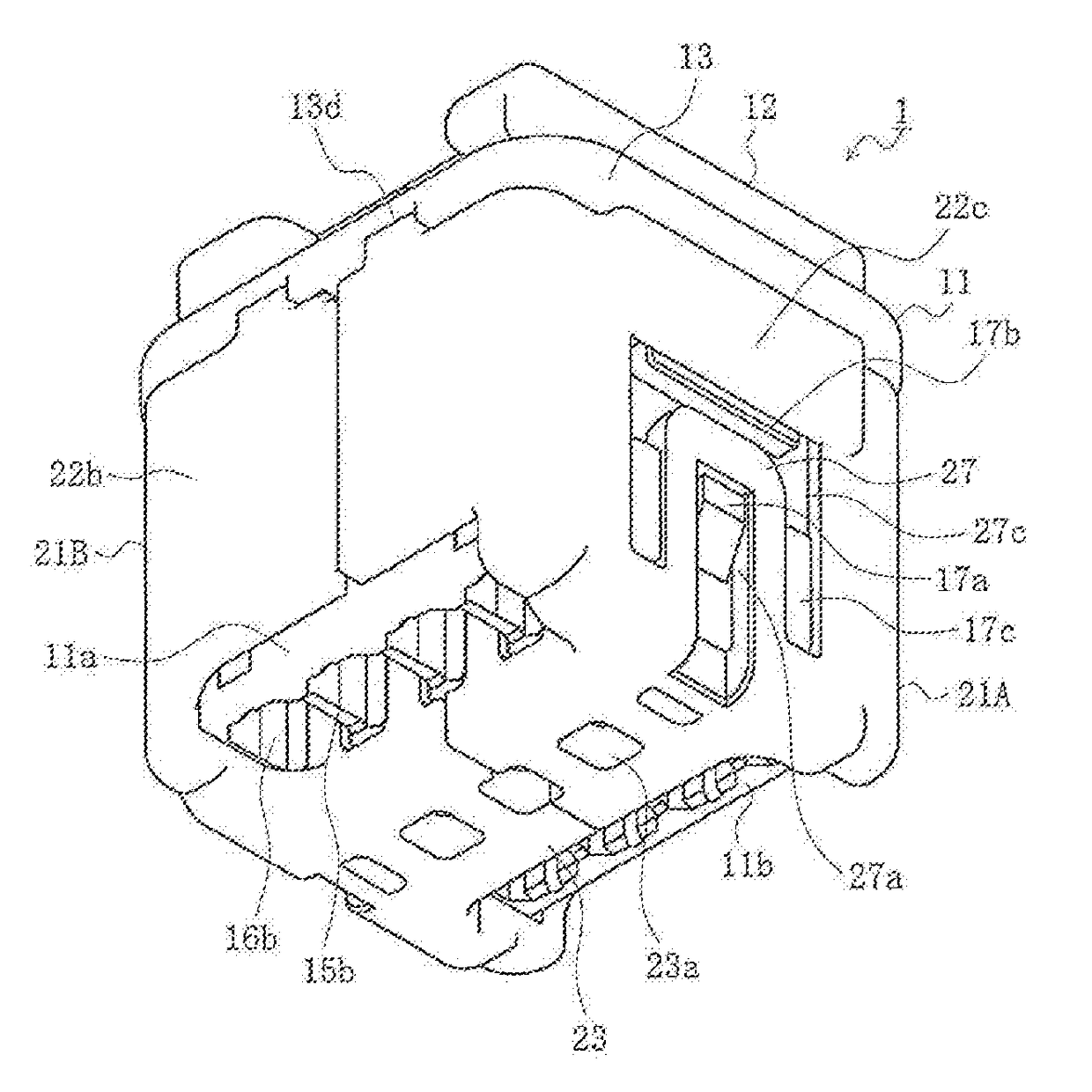
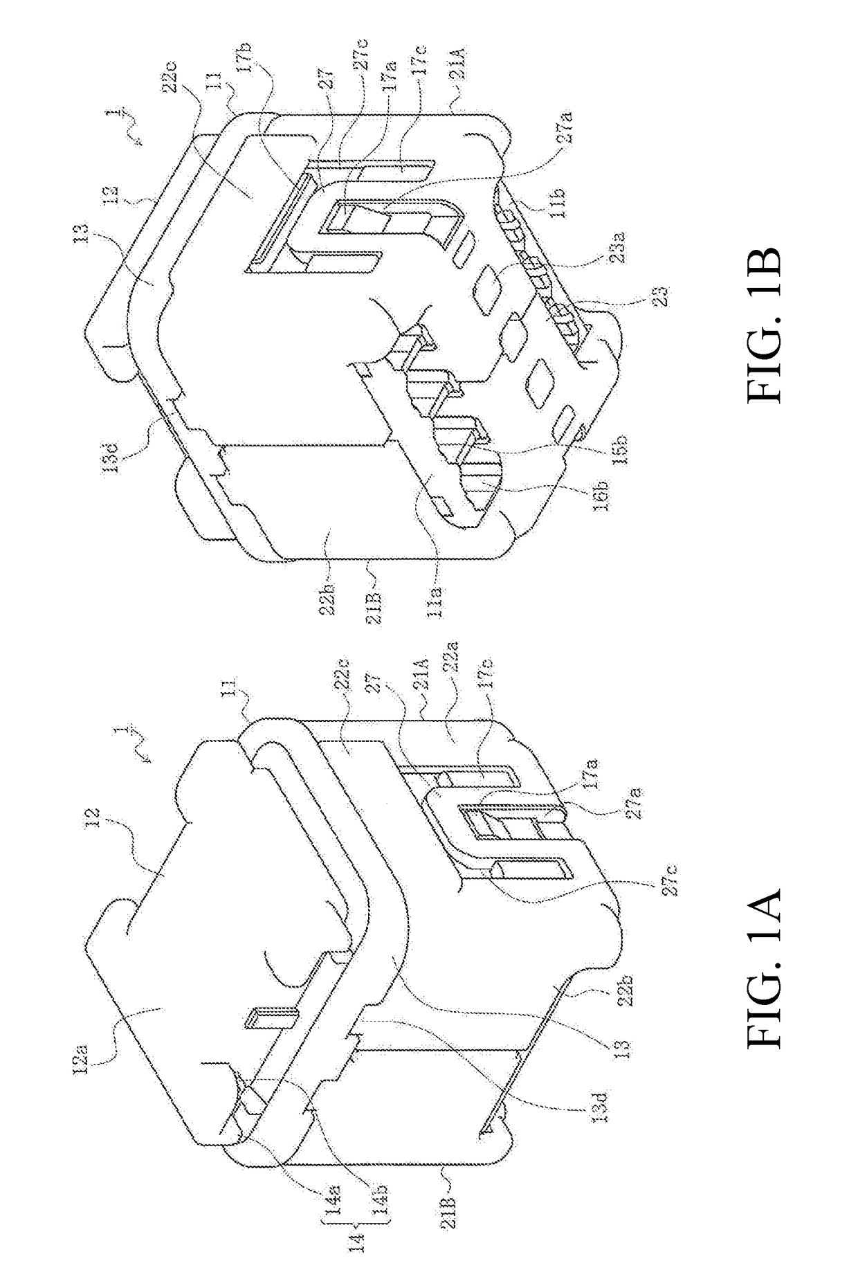
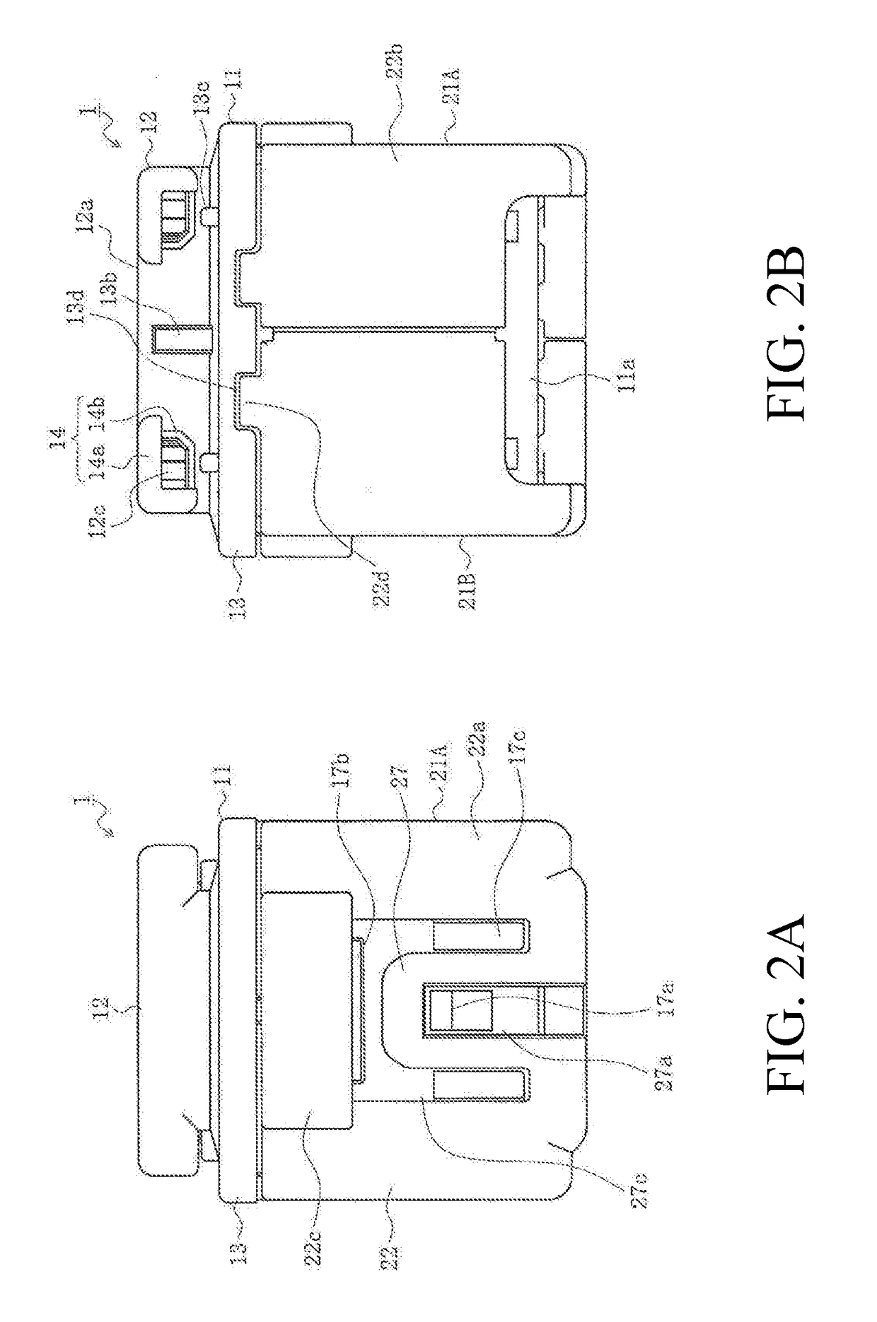
[0037]In these drawings, 1 denotes the connector in the present embodiment. The ends of a plurality of electrical wires 91 described below are connected to this connector.

[0038]This connector 1 may be used in various types of equipment and devices such as those in home electronics and automobiles. In the following explanation, however, it is used in equipment and devices installed outdoors such as in the outdoor unit of an air conditioner or in a hot tub installed outdoors. In other words, the connector is installed inside the equipment or device in a location exposed directly to rainwater despite a housing, case, or cover. The connector 1 does not have to be secured inside the equipment or device using a securing component and may change orientation.

[0039]In the present embodiment, the expressions indicating direction, such as upper, lower, left, right, front and rear, which are used to expl...


PUM


Abstract

A connector is provided which has terminals able to contact the opposing terminals connected to the terminal ends of electrical wires, and a housing accommodating the mounted terminals. The housing has a terminal accommodating recessed portion in the bottom end portion of the housing. The terminal accommodating recessed portion receives the inserted opposing terminals, and a head portion for sealing the upper end of the terminal accommodating recessed portion. The head portion includes a ceiling panel portion and side panel portions. Each side panel portion includes a water discharging hole communicating with the interior of the terminal accommodating recessed portion and outside of the housing, and a waterproofing rib formed around the water discharging hole and protruding from the outer surface of the side panel portion.

Description

RELATED APPLICATIONS[0001]This application claims priority to Japanese Application No. 2015-227535, filed Nov. 20, 2015, which is incorporated herein by reference in its entirety.TECHNICAL FIELD[0002]The present disclosure relates to a connector.BACKGROUND ART[0003]When a connector is used in an outdoor environment, waterproofing countermeasures are required to prevent direct exposure to rainwater. However, these waterproofing countermeasures increase the complexity of the structure of the connector and the size of the connector. Separate components such as a waterproof case and waterproof seal are required, and these increase costs.[0004]Instead of these waterproofing countermeasures, connectors have been proposed which are able to readily discharge any water that has entered to the outside, thereby reducing the complexity of the structure, the size of the connector, and costs. These connectors reduce corrosion of terminals to the extent that it no longer is a practical problem. (S...

Claims


Application Information

Patent Timeline
Patent Type & Authority Applications(United States)
IPC IPC(8): H01R13/52
CPCH01R13/5202H01R13/5213H01R13/5227H01R13/506H01R31/08H01R2201/26H01R12/774H01R13/4223H01R13/501
Inventor ITO, NAOTOSHIASAKAWA, KAZUSHIGECHIKANO, KOJI
Owner MOLEX INC
Why Eureka
Try Eureka