Camera positioning and orienting apparatus

a technology for positioning and orienting cameras, applied in the field of cameras, can solve the problems of not being specifically adapted for modern lightweight high definition video, complicated known devices, and high cost, and achieve the effects of enhancing the resistance of pivoting, high coefficient of friction, and easy adjustmen

Inactive Publication Date: 2017-05-25
LUOMA EUGENE H
View PDF4 Cites 17 Cited by
  • Summary
  • Abstract
  • Description
  • Claims
  • Application Information

AI Technical Summary

Benefits of technology

[0008]In embodiments of the invention, with regard to the base joint and the two joints on the proximal link portion and the two joints on the distal link member, each joint comprises at least one pair of cooperating joint components movable with respect to each other and defining the joint. Each pair of cooperating joint components with cooperating slidingly engaged joint surfaces. In embodiments, the cooperating joint surfaces are parallel, such as planar surfaces or partial spherical surfaces. The parallel cooperating surfaces and may have a high coefficient of friction with respect to each other that may be adjusted by varying clamping pressure between the respective surfaces. In embodiments at least one of pair of cooperating components comprises a component formed by overmolding or otherwise covering an exterior surface of one of the joint components with a polymer covering. The overmolded polymer may chemically adhere or be mechanically locked onto the base joint component. Polymers such as thermoplastic elastomers and more rigid polymers, such as polyethylenes, are suitable. In embodiments, the polymer has a durometer of 65 to 75 on the Shore A scale. In embodiments, the polymer has a durometer of 60 to 80 on the Shore A scale. The base joint component upon which the polymer overmolding is added may be formed of aluminum, steel, rigid polymers, or other structurally strong materials. In embodiments, the clamping force of the cooperating joint surfaces may be adjustably controlled by threaded members with manually graspable handles. In embodiments, the joints with an overmolded cooperating slidingly engaged joint surface provide easy adjustability for providing suitable resistance to sliding to maintain a camera stand with an extended arm against movement caused by gravity or other forces while still allowing each manual manipulation of the adjustable arm.
[0009]A feature and advantage of the invention is that a four bar linkage is pivotally attached to a base portion, a tube holder secures a vertical tube, a camera mount is positioned on the vertical tube, at least one joint of the four bar linkage has an overmolded cooperating joint component to provide enhanced resistance of pivoting.

Problems solved by technology

Such known devices are complicated, expensive, heavy, and not conducive to general consumer use, particularly where such devices are used for extending cameras outwardly, such as in a cantilevered manner, and then moving the cameras upwardly and downwardly.
Additionally, the ranges of motion such devices provide to cameras may be limited by joints that have incremental adjustment positions.
Moreover, such devices have not been specifically adapted for modern lightweight high definition video cameras

Method used


Image

  • Camera positioning and orienting apparatus
  • Camera positioning and orienting apparatus
  • Camera positioning and orienting apparatus

Examples


Embodiment Construction

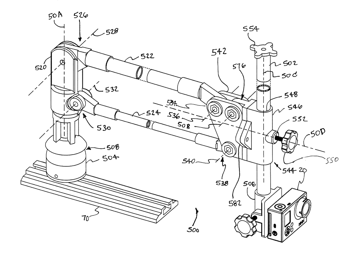
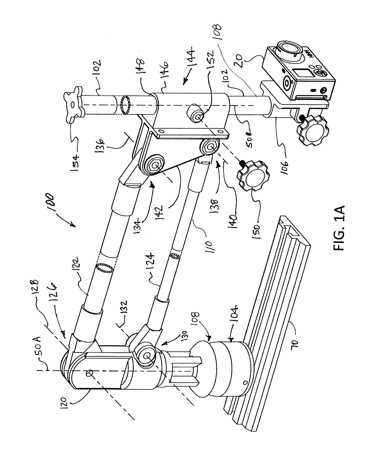
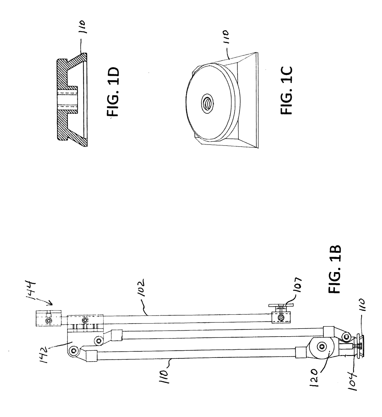
[0028]FIGS. 1A and 1B are views of camera stand 100 that may be used to position, orient and hold a camera 20, in a wide variety of locations and orientations within a space having three dimensions. A base portion 104 has a linkage 106 with a camera 20 attached to a distal portion 108 of the linkage at a camera mount 107. In the embodiment of FIG. 1, stand 100 includes a base assembly 104 that is attached to a mounting rail 70. As shown in FIG. 1, the base portion may be configured as a base assembly 104 and may be fixed to mounting rail 70 at various positions along a generally T-shaped slot in the mounting rail 70. In the embodiment of FIG. 1A, the base assembly 104 includes a pivoting joint 108 that provides three rotational degrees of freedom. The base portion may have other configurations as shown in FIG. 1B with a tripod adaptor 110. The pivoting movement provided by the pivoting joint 108 can be used to alter the position of the linkage and the attached camera.

[0029]In embodi...


PUM


Abstract

A camera stand comprises a base portion that may seat on or be suitably anchored on a floor surface, boat, dock, table, rail, vehicle, or other support structure. A horizontally and vertically adjustable linkage extends from the base portion and has the camera positioned at an end of the linkage. Means are provided for keeping the camera at a specific angle from horizontal as the adjustable linkage moves the camera about. Means are provided to provide joints in the linkage that have suitable resistance to unintended movement by gravity, wind or other forces and for which resistance to unintended movement is readily adjustable.

Description

CROSS-REFERENCE TO RELATED APPLICATION[0001]This application claims the priority to U.S. Provisional Application No. 62 / 259,333 with a filing date of Nov. 24, 2015. Said application is incorporated herein in its entirety.BACKGROUND[0002]The present disclosure relates to apparatus that may be used, for example, to place and hold an object, such as a camera in a wide variety of locations and orientations in a three dimensional space. The apparatus provides multiple degrees for freedom for positioning, orienting and holding the camera. Degrees of freedom in three dimensional spaces may be described with reference to a Cartesian coordinate system. It is customary to describe the Cartesian coordinate system by making reference to three orthogonal axes designated X, Y and Z. The term “degree of freedom” in this context means the ability of a body to translate along one of the three orthogonal X, Y, or Z axes shown (a translational degree of freedom) or to rotate about one of these three o...

Claims


Application Information

Patent Timeline
Patent Type & Authority Applications(United States)
IPC IPC(8): H04N5/225F16M11/28F16M11/38F16M13/02F16M11/20
CPCH04N5/2253F16M13/02F16M11/2092F16M2200/025F16M11/28F16M2200/063F16M2200/068F16M11/38F16M11/046F16M11/14F16M11/2021F16M11/2078F16M11/24F16M2200/022
Inventor LUOMA, EUGENE H.
Owner LUOMA EUGENE H
Why Eureka
Try Eureka