
Baffle insert for a gas turbine engine component and component with baffle insert

Active Publication Date: 2017-06-08
RAYTHEON TECH CORP
View PDF7 Cites 11 Cited by
  • Summary
  • Abstract
  • Description
  • Claims
  • Application Information

AI Technical Summary

Benefits of technology

The patent describes a baffle insert for a gas turbine engine that has a plurality of trip strips and at least one rib on its exterior surface. The baffle insert is designed to be inserted into an internal cooling cavity of the engine. The technical effects of the patent include improved cooling efficiency, reduced pressure drop, and improved airflow control. The patent also describes different configurations for the plurality of trip strips and the at least one rib, such as a crosshatch configuration and a spiral configuration.

Problems solved by technology

High combustion temperatures also increase thermal and mechanical loads, particularly on turbine airfoils downstream of the combustor.
This reduces service life and reliability, and increases operational costs associated with maintenance and repairs.

Method used


Image

  • Baffle insert for a gas turbine engine component and component with baffle insert
  • Baffle insert for a gas turbine engine component and component with baffle insert
  • Baffle insert for a gas turbine engine component and component with baffle insert

Examples


Embodiment Construction

[0121]Various embodiments of the present disclosure are related to cooling techniques for airfoil sections of gas turbine components such as vanes or blades of the engine. In particular, the present application is directed to an insert or baffle or baffle insert used in conjunction with cooling passages of the airfoil.

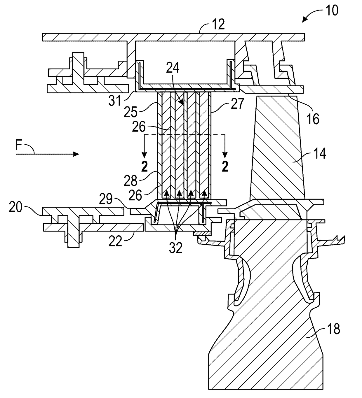
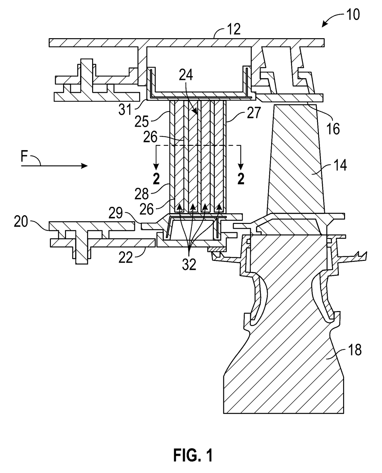
[0122]FIG. 1 is a cross-sectional view of a portion of a gas turbine engine 10 wherein various components of the engine 10 are illustrated. These components include but are not limited to an engine case 12, a rotor blade 14, a blade outer air seal (BOAS) 16, a rotor disk 18, a combustor panel 20, a combustor liner 22 and a vane 24. As mentioned above, vane or component 24 is subjected to high thermal loads due to it being located downstream of a combustor of the engine 10. Thus, it is desirable to provide cooling to the airfoils of the engine.

[0123]In order to provide cooling air to the vane 24, a plurality of cooling openings or cavities 26 are formed within an airfoi...


PUM


Abstract

A component of a gas turbine engine having: an internal cooling cavity; a baffle insert configured to be inserted into the internal cooling cavity; a plurality of trip strips extending upwardly from an exterior surface of the baffle insert; at least one separating feature located between a pair of ends of a pair of the plurality of trip strips, wherein the plurality of trip strips and the at least one separating feature are spaced from an interior surface of the internal cooling cavity; a plurality of trip strips extending upwardly from the interior surface; and at least one separating feature located between a pair of ends of the plurality of trip strips located on the interior surface of the internal cooling cavity, wherein the plurality of trip strips and the at least one separating feature of the interior surface are spaced from the exterior surface of the baffle insert.

Description

BACKGROUND[0001]This disclosure relates generally to gas turbine engines and, more particularly, to cooling techniques for the airfoil sections of turbine blades and / or vanes of the engine. In particular, the present application is directed to an insert for use in convective cooling of the airfoils of the gas turbine engine which are exposed to high-temperature working fluid flow.[0002]In general, gas turbine engines are built around a power core comprising a compressor, a combustor and a turbine, which are arranged in flow series with a forward (upstream) inlet and an aft (downstream) exhaust. The compressor compresses air from the inlet, which is mixed with fuel in the combustor and ignited to produce hot combustion gases. The hot combustion gases drive the turbine section, and are exhausted with the downstream flow.[0003]The turbine drives the compressor via a shaft or a series of coaxially nested shaft spools, each driven at different pressures and speeds. The spools employ a nu...

Claims


Application Information

Patent Timeline
IPC IPC(8): F01D5/18F01D25/12F01D11/08F23R3/00F01D9/02
CPCF01D5/189F23R3/002F01D9/02F05D2240/35F01D25/12F05D2220/32F05D2260/22141F01D11/08F01D5/188F05D2240/126F05D2260/204F05D2260/2212F05D2240/127F05D2250/25
Inventor SPANGLER, BRANDON W.KOHLI, ATUL
Owner RAYTHEON TECH CORP
Learn More