Engine cooling device for vehicle

a cooling device and engine technology, applied in the direction of machines/engines, mechanical equipment, transportation and packaging, etc., can solve the problem of preventing damage due to freezing of the cooling liquid circulating circuit that has been cut off, and achieves the effect of reducing the damage of the cooling liquid circulating circui

Active Publication Date: 2017-06-08
TOYOTA JIDOSHA KK
View PDF9 Cites 19 Cited by
  • Summary
  • Abstract
  • Description
  • Claims
  • Application Information

AI Technical Summary

Benefits of technology

[0015]Further, as in a fourth aspect of the present invention, in a case in which the ignition switch is turned on, the control section may further control the switching section to maintain the communicating state until non-freezing of the cooling liquid is detected. Due thereto, the cooling liquid freezing and the circulating circuit being damaged at the time when the ignition switch is turned on and the state transitions from the communicating state to the cut-off state, can be prevented. Note that, in this case, as in the fifth aspect of the present invention, the non-freezing of the cooling l...

Problems solved by technology

However, in JP-A No. 2000-257430, in a case of providing a cooling liquid circulating circuit that is provided so as to be able to be cut-off from an engine cooling circuit that includes the ra...

Method used


Image

  • Engine cooling device for vehicle
  • Engine cooling device for vehicle
  • Engine cooling device for vehicle

Examples


first embodiment

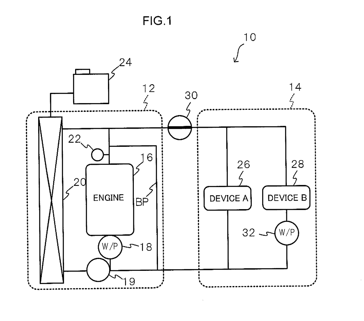
[0028]FIG. 1 is a schematic drawing showing the schematic structure of an engine cooling device for a vehicle relating to the present embodiment. An engine cooling device 10 for a vehicle relating to the present embodiment has plural circulating circuits for circulating cooling water that serves as a cooling liquid. Concretely, the present embodiment describes an example in which, as shown in FIG. 1, the engine cooling device 10 for a vehicle has two circulating circuits that are a circulating circuit A 12 that serves as an engine cooling circuit, and a circulating circuit B 14 that serves as a cooling liquid circulating circuit.

[0029]The circulating circuit A 12 is a circulation path at which cooling water circulates through an engine 16 that serves as a heat generating body, and the cooling water is circulated by an engine water pump (W / P) 18 that serves as a circulating section. The cooling water circulates in a water jacket within the engine 16. In detail, a radiator 20, that se...

second embodiment

[0056]An engine cooling device for a vehicle relating to a second embodiment is described next. In the engine cooling device for a vehicle relating to the second embodiment, only the processings that are carried out at the control section 40 differ with respect to the first embodiment, and therefore, description of the structure is omitted.

[0057]In the second embodiment, after the ignition switch is turned off, the temperature of the cooling water within the circulating circuits is made uniform due to the water pumps (the ENG water pump 18 and the water pump 32) being operated. Namely, when the circulating circuit A 12 freezes first and subsequently the circulating circuit B 14 freezes, the pressure of the circulating circuit B 14 cannot escape to the reservoir tank 24. Therefore, this is prevented by making the temperature of the cooling water within the circulating circuits uniform.

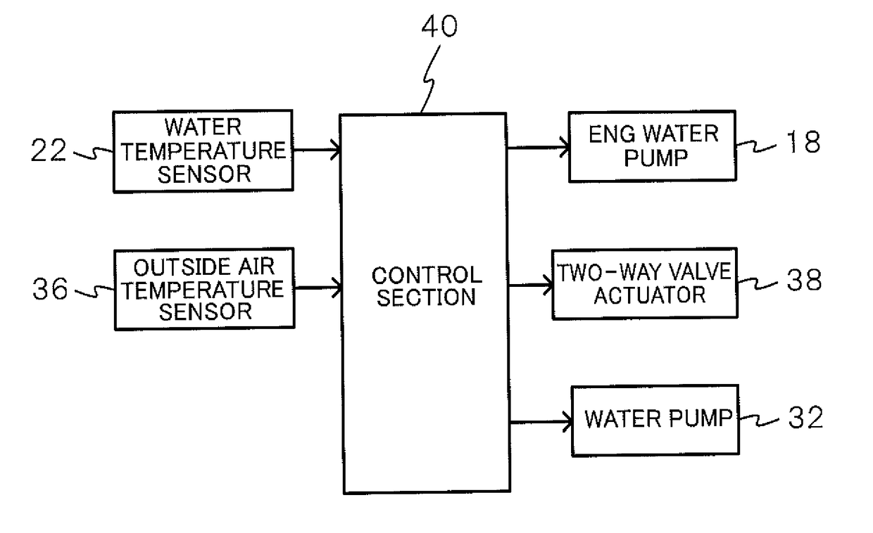
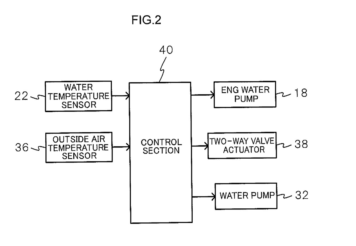
[0058]FIG. 4 is a flowchart showing some of the processings that are carried out by the control sect...

third embodiment

[0072]An engine cooling device for a vehicle relating to a third embodiment is described next. FIG. 5 is a schematic drawing showing the schematic structure of an engine cooling device for a vehicle relating to the present embodiment. Note that structures that are the same as those of the first embodiment are denoted by the same reference numerals, and detailed description thereof is omitted.

[0073]The above-described respective embodiments describe examples in which two circulating circuits that circulate the cooling water are provided. However, the present embodiment describes an example in which three circulating circuits are provided. Namely, as shown in FIG. 5, an engine cooling device 11 for a vehicle relating to the present embodiment has the circulating circuit A 12, the circulating circuit B 14 and the circulating circuit C 42, and the circulating circuit C 42 is added as a cooling liquid circulating circuit to the above-described embodiments.

[0074]The circulating circuit A ...


PUM


Abstract

An engine cooling device for a vehicle of the present invention includes: an engine cooling circuit that circulates a cooling liquid to an engine and a heat exchanger; a reservoir tank that is connected to the engine cooling circuit, and that stores the cooling liquid to absorb pressure changes within the engine cooling circuit; at least one or more cooling liquid circulating circuits that circulates the cooling liquid to devices installed in the vehicle; a switching section that selectively switches between either of a communicating state of communicating the engine cooling circuit and the cooling liquid circulating circuit, and a cut-off state of cutting-off the engine cooling circuit and the cooling liquid circulating circuit; and a control section that, in a case in which an ignition switch is turned off, controls the switching section such that the communicating state is set.

Description

CROSS-REFERENCE TO RELATED APPLICATION[0001]This application claims priority under 35U.S.C. 119 from Japanese Patent Application No. 2015-238527 filed Dec. 7, 2015, the disclosure of which is incorporated by reference herein.BACKGROUND[0002]Technical Field[0003]The present disclosure relates to an engine cooling device for a vehicle that circulates a liquid to an engine and cools the engine,[0004]Related Art[0005]Japanese Patent Application Laid-Open (JP-A) No. 2000-257430 proposes a cooling device of an internal combustion engine that has a freezing prevention mechanism that, before the outside air temperature drops and cooling liquid freezes at the time when an engine is stopped, recovers some of the cooling liquid, that is within a freezing prevention tube and a water jacket, into a reservoir tank. By providing a freezing prevention mechanism in this way, damage to the engine and the circulation path of the cooling liquid and the like due to volumetric expansion caused by freezin...

Claims


Application Information

Patent Timeline
IPC IPC(8): F01P7/16F01P11/20F01P3/20F01P11/02F01P5/10
CPCF01P7/16F01P11/029F01P5/10F01P3/20F01P11/20F01P2060/00F01P2025/13F01P2025/08F01P2037/02F01P2023/08F01P2031/30F01P7/165F01P2050/22B60K11/02B60H1/00278B60H1/08F01P2005/105F01P2007/146F01P2025/32F01P2031/24F01P2060/08F01P2060/16F02M26/00B60H1/32281
Inventor ONISHI, YOICHIKAKEHASHI, NOBUHARU
Owner TOYOTA JIDOSHA KK
Why Eureka
Try Eureka