
Method and apparatus for eddy current field compensation in magnetic resonance tomography

a magnetic resonance tomography and compensation method technology, applied in the field of eddy current field compensation in magnetic resonance tomography, can solve the problems of reducing quality and affecting the resulting image, and achieve the effects of reducing the eddy current field, improving image quality, and reducing the cos

Active Publication Date: 2017-06-08
SIEMENS HEALTHCARE GMBH
View PDF13 Cites 4 Cited by
  • Summary
  • Abstract
  • Description
  • Claims
  • Application Information

AI Technical Summary

Benefits of technology

The invention explains a method for improving the accuracy and quality of magnetic resonance imaging (MRI) by compensating for eddy currents that occur in conductive components of the MRI apparatus. By taking into account the sensed value of the eddy current field, the method increases the precision of eddy current compensation and makes the magnetic fields more uniform, resulting in better image quality. This is particularly useful in magnetic resonance apparatuses that have conductive components that can form strong eddy currents and are subject to temperature fluctuations. The method calculates the sensed value of the structure where eddy currents are formed and uses it to determine the abatement characteristic of the eddy currents. This further increases accuracy, especially when there is a significant contribution of eddy currents to the field. Temperature fluctuations can also be accounted for in the eddy current field compensation. The method can reduce the required data and scanning time for eddy current field compensation by using a precise model that takes into account the characteristics of the MRI device.

Problems solved by technology

The eddy currents in turn magnetically generate eddy current fields that impair the resulting images in magnetic resonance tomography and reduce the quality thereof.

Method used


Image

  • Method and apparatus for eddy current field compensation in magnetic resonance tomography
  • Method and apparatus for eddy current field compensation in magnetic resonance tomography
  • Method and apparatus for eddy current field compensation in magnetic resonance tomography

Examples


Embodiment Construction

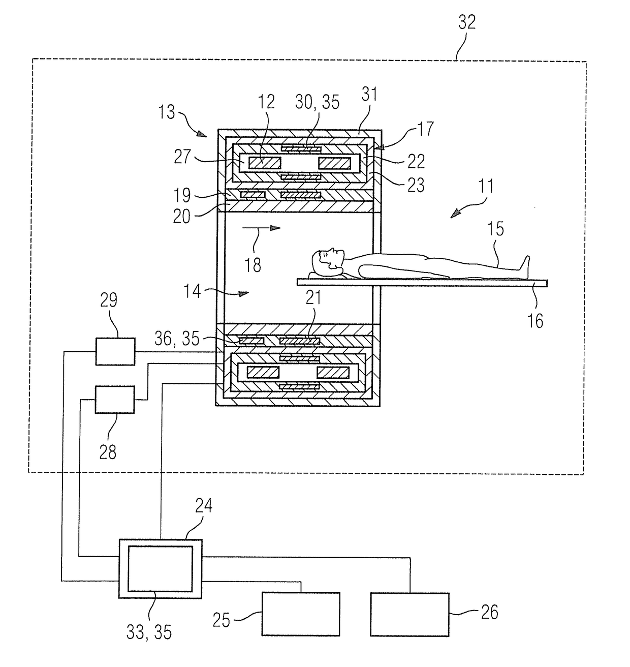
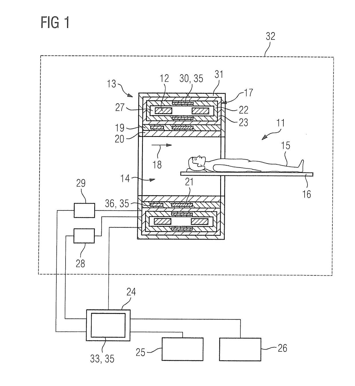
[0086]FIG. 1 shows a magnetic resonance apparatus according to the invention 11 in a schematic illustration. The magnetic resonance apparatus 11 has a scanner 13 with a basic field magnet 17. The basic field magnet 17 has magnetic coils 12 made of superconductive material for generating a strong and constant basic magnetic field 18. The magnetic coils 12 are located in a helium vessel 27, which is typically manufactured of stainless steel and is filled with liquid helium to cool the magnetic coils 12. The helium vessel 27 is in the form of a hollow cylinder and is surrounded by a cooling shield 22, likewise in the form of a hollow cylinder. The cooling shield 22 can be made of aluminum and typically has a temperature of 60 Kelvin in the operational state of the magnetic resonance apparatus 11. The cooling shield 22 is in turn surrounded by a vacuum chamber 23, which seals the basic field magnet 17 from the external environment. The vacuum chamber 23 is typically made of stainless st...


PUM


Abstract

In a method and an apparatus for magnetic resonance tomography, an eddy current field is compensated by taking into account its progression over time and its dependence on a sensed value, by having a sensor determine the sensed value and, on the basis of the sensed value, a current strength for a conductor in order to generate an opposing field to reduce the eddy current field is determined, and supplied to the conductor.

Description

BACKGROUND OF THE INVENTION[0001]Field of the Invention[0002]The present invention concerns a method for reducing an eddy current field in magnetic resonance tomography. The present invention further concerns a magnetic resonance apparatus that is designed to implement such a method.[0003]Description of the Prior Art[0004]In magnetic resonance tomography, magnetic field gradients generated by gradient coils are used for spatially encoding the magnetic resonance signals. The magnetic field gradients will switch on and off within milliseconds, which is why, due to induction, eddy currents are formed on the conductive structures surrounding the gradient coils. The eddy currents in turn magnetically generate eddy current fields that impair the resulting images in magnetic resonance tomography and reduce the quality thereof. A key factor in the generation of eddy current fields is due to structures in the magnetic resonance device that have a high electrical conductivity. Depending on th...

Claims


Application Information

Patent Timeline
Patent Type & Authority Applications(United States)
IPC IPC(8): G01R33/389G01R19/00G01R33/38G01R33/385G01R33/3815
CPCG01R33/389G01R33/385G01R19/0092G01R33/3804G01R33/3815G01R33/56518
Inventor BIBER, STEPHANGEBHARDT, MATTHIASKRUG, ANDREAS
Owner SIEMENS HEALTHCARE GMBH
Learn More