Amplitued calibration of a stepped-chirp signal for a synthetic aperture radar

a synthetic aperture radar and amplitued calibration technology, applied in the field of radar systems, can solve the problems of increasing the bandwidth of transmitted signals beyond certain points, poor azimuth resolution of the target area formed by the slar, and difficult to physically implement in reality

Active Publication Date: 2017-06-08
THE BOEING CO
View PDF1 Cites 28 Cited by
  • Summary
  • Abstract
  • Description
  • Claims
  • Application Information

AI Technical Summary

Problems solved by technology

As such, the image of the target area formed by a SLAR is poor in azimuth resolution because the azimuth antenna beamwidth has an angular resolution that is too broad to differentiate between fine details at the same range within the target area.
Therefore for an SLAR, either an extremely large antenna or very high frequency of operation (where the wavelengths are so short that the radar must content with the effects of severe attenuation in the atmosphere) needs to be utilized to produce high resolution images of target areas for direct terrain mapping and/or remote sensing, which is unrealistic for a radar system installed on a moving platform.
Unfortunately, although it is true that in theory the range resolution may be improved by utilizing a wideband signal, it is also true that, in practice, increasing the bandw

Method used


Image

  • Amplitued calibration of a stepped-chirp signal for a synthetic aperture radar
  • Amplitued calibration of a stepped-chirp signal for a synthetic aperture radar
  • Amplitued calibration of a stepped-chirp signal for a synthetic aperture radar

Examples


Embodiment Construction

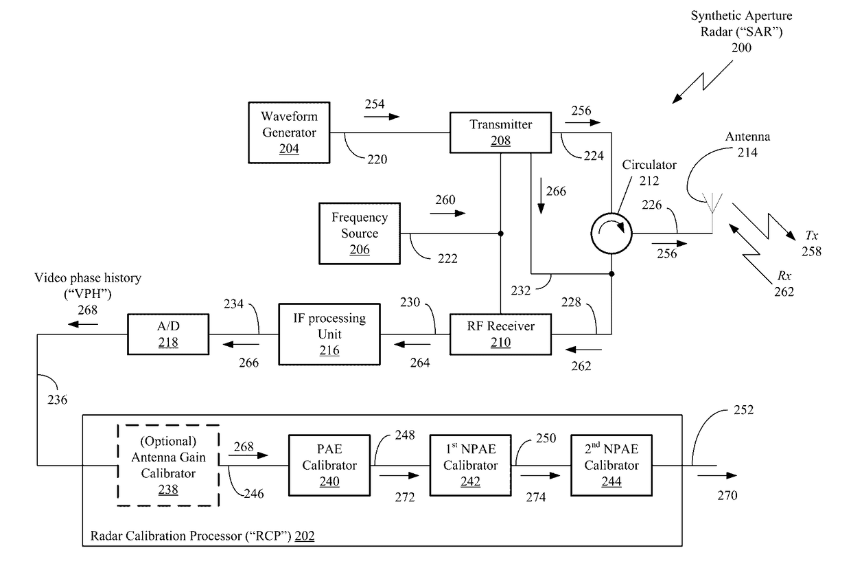
[0057]Disclosed is a Radar Calibration Processor (“RCP”) for calibrating the amplitude of a stepped-chirp signal utilized by a synthetic aperture radar (“SAR”). The RCP includes a periodic amplitude error (“PAE”) calibrator, first non-periodic amplitude error (“NPAE”) calibrator in signal communication with the PAE calibrator, and a second NPAE calibrator in signal communication with the first NPAE calibrator.

[0058]In an example of operation, the RCP preforms a method that calibrates the amplitude of the stepped-chirp signal by receiving SAR image data from an acquired radar target area that was scanned with a SAR utilizing a plurality of stepped-chirp signals and calibrating the amplitudes of the stepped-chirp signals. The calibration of the amplitudes is performed by estimating the amplitudes errors in the stepped-chirp signals. The RCP performs this method by sequentially first calibrating the SAR image data with the PAE calibrator to remove periodic amplitude errors in the SAR i...


PUM


Abstract

A Radar Calibration Processor (“RCP”) for calibrating the amplitude of a stepped-chirp signal utilized by a synthetic aperture radar (“SAR”) is disclosed. The RCP includes a periodic amplitude error (“PAE”) calibrator, first non-periodic amplitude error (“NPAE”) calibrator in signal communication with the PAE calibrator, and a second NPAE calibrator in signal communication with the first NPAE calibrator.

Description

CROSS-REFERENCE To RELATED APPLICATIONS[0001]This application is related to U.S. patent application Ser. No. ______, titled “PHASE CALIBRATION OF A STEPPED-CHIRP SIGNAL FOR A SYNTHETIC APERTURE RADAR,” filed on the same day, ______, to inventors Kwang M. Cho, which is herein incorporated by reference in its entirety.STATEMENT REGARDING FEDERALLY SPONSORED RESEARCH AND DEVELOPMENT[0002]This invention was made with United States Government (“USG”) support. The government has certain rights in the invention.BACKGROUND OF THE INVENTION[0003]1. Field of the Invention[0004]The present disclosure is generally related to radar systems and more specifically to correcting errors in Synthetic Aperture Radar (“SAR”) data.[0005]2. Related Art[0006]Radar has long been used for military and non-military purposes in a wide variety of applications such as imaging, guidance, remote sensing and global positioning. A Synthetic Aperture Radar (“SAR”) is a coherent mostly airborne or spaceborne side-look...

Claims


Application Information

Patent Timeline
IPC IPC(8): G01S7/40G01S13/90
CPCG01S13/90G01S7/4004G01S7/40G01S13/282
Inventor CHO, KWANG M.CONTE, KENNETH W.
Owner THE BOEING CO
Why Eureka
Try Eureka