Direct digital synthesizing method and direct digital synthesizer

a digital synthesizer and digital frequency technology, applied in the field of digital signal processing, can solve the problems of high frequency accuracy, limited application range, and high frequency accuracy of the conventional dds, and achieve the effects of improving accuracy, reducing errors, and increasing accuracy

Active Publication Date: 2017-06-08
CSMC TECH FAB2 CO LTD
View PDF5 Cites 4 Cited by
  • Summary
  • Abstract
  • Description
  • Claims
  • Application Information

AI Technical Summary

Benefits of technology

[0021]Because processing of the conventional DDS always has the phase truncation error, but the above direct digital frequency synthesis method and direct digital frequency synthesizer can reflect the phase truncation degree by comparing and processing the phase again, and compensation can be performed in the case that the phase is truncated much more, for reducing error and improving accuracy. Meanwhile, a plurality of phases usually correspond to a same sinusoidal value in the sinusoidal lookup table, and depth of the sinusoidal lookup table is at least 4 times higher than the resolution of the sinusoidal output. If the truncation error is reduced by increasing accuracy, then the cost will be relatively higher. However, the additional phase lookup table is formed by the manner that one sinusoidal value corresponds to one phase boundary value, therefore, depth of the phase lookup table is commensurate with the resolution of the sinusoidal output, which can efficiently eliminate the phase error based on the required sinusoidal resolution, and the cost will not be much high.

Problems solved by technology

In some applications that the frequency of the sinusoidal wave needs to be adjusted, adjustability for the frequency is demanding.
Therefore, the frequency accuracy that the conventional DDS can actually output is very limited, and then the application range is also limited.
However, depth of the sinusoidal lookup table and the address size has an exponential relation, so a huge sinusoidal lookup table cannot be built in a reasonable cost to reduce the phase error.

Method used


Image

  • Direct digital synthesizing method and direct digital synthesizer
  • Direct digital synthesizing method and direct digital synthesizer
  • Direct digital synthesizing method and direct digital synthesizer

Examples


Embodiment Construction

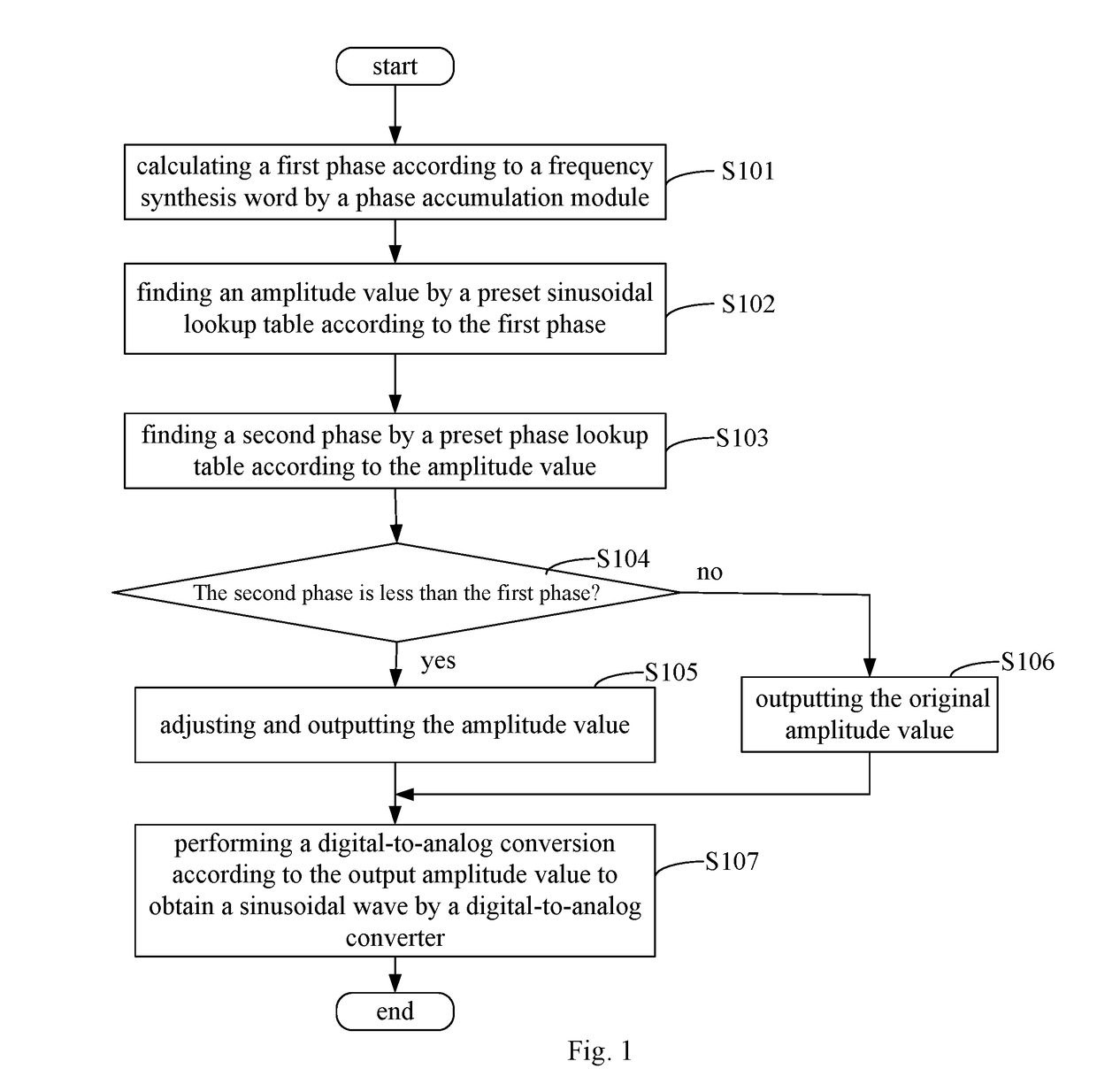
[0027]Referring to FIG. 1, in an embodiment, a direct digital frequency synthesis method includes the following steps:

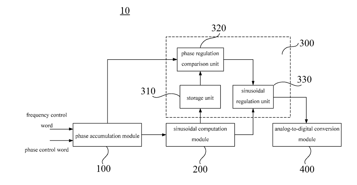
[0028]In step S101: a phase accumulation module calculates a first phase according to a frequency synthesis word. In DDS, the frequency synthesis word is also called a frequency control code, which is the data input by the user and configured to control frequency adjustment. The frequency synthesis word is stored in the frequency control register. The phase accumulation module performs the accumulation operation within each clock cycle according to the frequency synthesis word to obtain a phase value which is called a first phase in the embodiment.

[0029]In step S102: an amplitude value is looked up by a preset sinusoidal lookup table according to the first phase. The preset sinusoidal lookup table is a lookup table the address of which is the phase and the content of which is the amplitude value. The conventional lookup table is implemented by using the chip having r...


PUM


Abstract

A direct digital frequency synthesis method comprises the following steps: calculating, by a phase accumulation module, a first phase according to a frequency synthesis word (S101); finding an amplitude value by a preset sinusoidal lookup table according to the first phase (S102); finding a second phase by a preset phase lookup table according to the amplitude value (S103); if the second phase is less than the first phase, adjusting and outputting the amplitude value (S105); or else, outputting the original amplitude value (S106); and performing, by a digital-to-analog converter, a digital-to-analog conversion according to the output amplitude value to obtain a sinusoidal wave (S107); wherein, for a N-bit phase accumulation module and a D-bit digital-to-analog converter, the preset phase lookup table has 2D−1-1 phase boundary value records corresponding to 0˜2D−1-2 amplitudes, each phase boundary value is stored in N-2 bits. A direct digital frequency synthesizer applying the above method is also disclosed.

Description

FIELD OF THE INVENTION[0001]The present invention relates to digital signal processing, and particularly relates to a direct digital frequency synthesis method and a direct digital frequency synthesizer.BACKGROUND OF THE INVENTION[0002]In some applications that the frequency of the sinusoidal wave needs to be adjusted, adjustability for the frequency is demanding. For example, adjustment of the resonant frequency of the gyroscope sensor of PZT architecture. Adjustability for the frequency thereof reaches below 0.1 Hz. DDS (Direct Digital Synthesizer) provides a method of accurately controlling the sinusoidal frequency in a digital manner.[0003]The working principle of DDS is that based on the characteristic that the sinusoidal wave circulates once in every 2π phase angle, the 0˜2π phase is evenly divided into 2N units by using the phase accumulation module (N-bit), and then according to different requirements for frequency, an angle of frequency word is added into the phase accumula...

Claims


Application Information

Patent Timeline
Patent Type & Authority Applications(United States)
IPC IPC(8): H03L7/16
CPCH03L7/16G06F1/022G06F1/0321
Inventor WU, HUAGANG
Owner CSMC TECH FAB2 CO LTD
Why Eureka
Try Eureka