
Three Section Threshing Concave Configuration and Adjustment Mechanism for an Agricultural Harvesting Combine

a concave and combine technology, applied in the field of articulated (jointed) combine harvesting, can solve the problems of limited openings in the forward portion of the concave, grain to be shaken out of straw, risking damage to grain, etc., and achieve the effect of preventing wide gap spaces between concave inserts

Active Publication Date: 2017-06-15
TRIBINE IND
View PDF5 Cites 26 Cited by
  • Summary
  • Abstract
  • Description
  • Claims
  • Application Information

AI Technical Summary

Benefits of technology

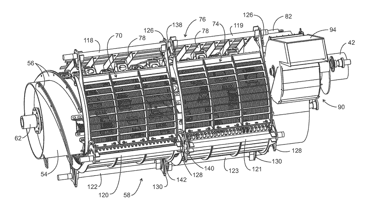
This patent describes a rotor and cage assembly with a skeleton of curved spaced-apart side members and horizontal members, as well as concave inserts that interlace with straight fingers for different types of grain. A control assembly of plates and bars connects to the skeleton and can synchronize the rotation of the plates to move the interlacing concave inserts closer together or farther apart for different types of grain. A grate assembly surrounds the rotor for separating grain and also has concave inserts that can be adjusted using the control assembly. Overall, the patent describes how to efficiently and adjustably process different types of grain using a rotor and cage assembly with concave inserts.

Problems solved by technology

The function of typical straight bars is to disrupt the consistent flow that shorter rasp bars establish and, thereby, cause grain to be shaken out of the straw due to that turbulence.
The number and size of openings in the forward portion of the concave is limited, however, and it has been observed that some of the threshed grain travels over additional rasp bars or other threshing surfaces on the rotor prior to falling through an opening of the concave.
As a result, the grain remains in the threshing system longer, encountering more threshing elements, risking damage to the grain, and increasing the likelihood that the cobs will break.

Method used


Image

  • Three Section Threshing Concave Configuration and Adjustment Mechanism for an Agricultural Harvesting Combine
  • Three Section Threshing Concave Configuration and Adjustment Mechanism for an Agricultural Harvesting Combine
  • Three Section Threshing Concave Configuration and Adjustment Mechanism for an Agricultural Harvesting Combine

Examples


Embodiment Construction

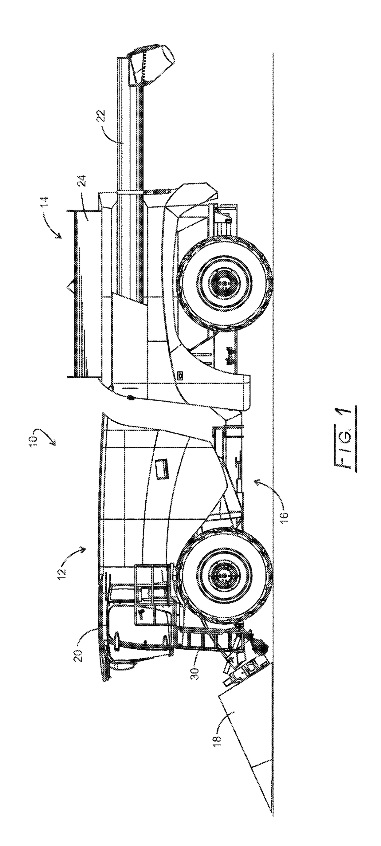
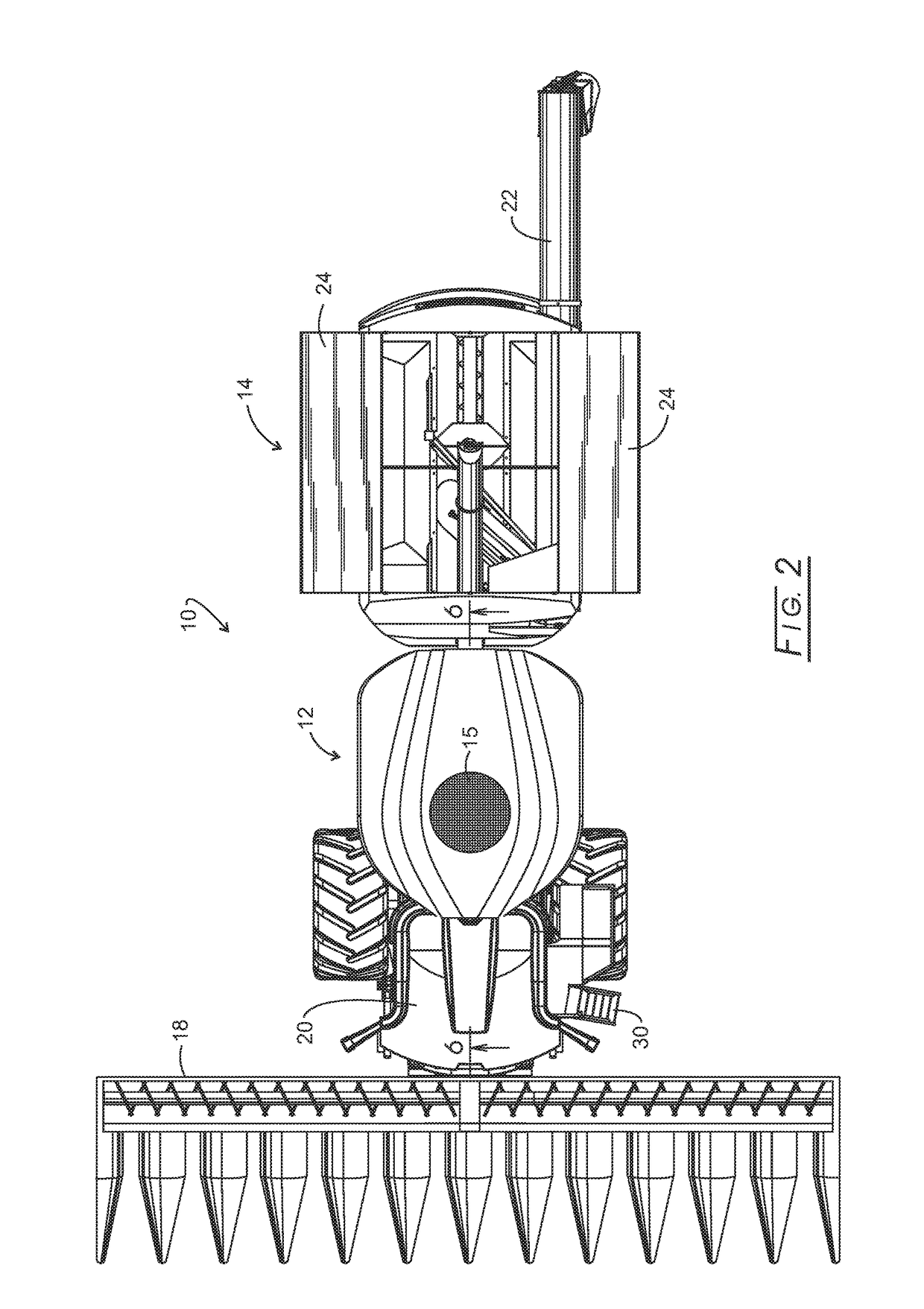
[0041]Referring initially to FIGS. 1, 2, 3, and 4, an articulated harvester, 10, consists of a powered PPU, 12, a rear grain cart, 14, and an articulation joint, 16, that connects PPU 12 with rear grain cart 14. The details of articulation joint 16 are disclosed in commonly owned application Ser. No. 14 / 946,827 filed Nov. 20, 2015. PPU 12 carries a grainhead, 18, operator's cab, 20, grain cleaning and handling assembly, and engines. PPU 12 is devoid of any grain storage, such being exclusive in rear grain cart 14. While both PPU 12 and rear grain cart 14 are shown being carried by wheel assemblies, one or both could be tracked. A screened air inlet, 15, is located atop PPU 12 where the air likely is the cleanest around harvesting combine 10.

[0042]An off-loading auger assembly, 22, is in the folded home position and being carried by rear grain cart 14. Grain cart 14 also bears a foldable roof, 24, shown in an open position, but which can fold inwardly to cover grain stored in rear gr...


PUM


Abstract

Disclosed is a rotor and cage assembly that includes a skeleton of curved spaced-apart side members affixed to laterally extending upper and lower spaced-apart members therebetween and surrounding the rotor. One of the curved spaced-apart side members is terminated with curved fingers. Three concave inserts insert laterally into the skeleton spanning 270° around the rotor. One of the concave inserts carries straight fingers that interlace between the skeleton side member curved fingers. A control assembly of plates having arcuate slots placed at 3 of the pivots of the skeleton assembly, control bars connected to the skeleton pivots, and an actuator connect to the control bars at one end effect arcuate rotation of the control bars resulting in the synchronized rotation of the arcuate slotted plates so that the interlaced straight fingers move closer together or farther apart with the fixed skeleton assembly curved fingers for different types of grain.

Description

CROSS-REFERENCE TO RELATED APPLICATIONS[0001]None.STATEMENT REGARDING FEDERALLY SPONSORED RESEARCH[0002]Not applicable.BACKGROUND[0003]The present disclosure relates to harvesting articulated (jointed) combines and more particularly to improved concaves in the forward tractor or crop processing power unit (PPU).[0004]Most agricultural combines use a rotary threshing and / or separating system including at least one rotor drivingly rotated about a rotational axis within a rotor housing, the housing having a lower region including a perforated concave spaced radially outwardly of the rotor. The rotor often may have a frusto-conical inlet end having a helical flight or flights therearound for conveying a flow of crop material into the space between the rotor and the housing. The main body of the rotor typically will have an array or layout of threshing elements, most commonly including rasp bars and separating elements, and / or elongated tines, all of which protrude radially outwardly the...

Claims


Application Information

Patent Timeline
Patent Type & Authority Applications(United States)
IPC IPC(8): A01F7/06
CPCA01F7/062A01F7/067A01F7/06A01F12/22A01F12/26A01F12/28A01D69/00
Inventor MATOUSEK, ROBERT A.CLAERHOUT, ROGER
Owner TRIBINE IND
Learn More