Imprint apparatus and method of imprinting a partial field

a technology of imprinting apparatus and partial field, which is applied in the field of imprinting apparatus, can solve the problems of particular challenges in imprinting a partial field

Active Publication Date: 2017-06-15
CANON KK
View PDF3 Cites 12 Cited by
  • Summary
  • Abstract
  • Description
  • Claims
  • Application Information

AI Technical Summary

Problems solved by technology

While imprinting any field may be challenging, imprinting a partial field can be particularly challenging.

Method used


Image

  • Imprint apparatus and method of imprinting a partial field
  • Imprint apparatus and method of imprinting a partial field
  • Imprint apparatus and method of imprinting a partial field

Examples


embodiment 1

[0074] An imprint apparatus comprising[0075]a substrate holder including a chucking region and a recessed support section adjacent to a periphery of the chucking region, wherein the chucking region has a chucking region area; and[0076]a template holder having a template region for a template, wherein the template region has a template region area,[0077]wherein the chucking region area is larger than the template region area.

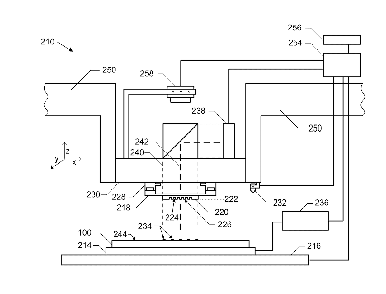
[0078]Embodiment 2. The imprint apparatus of Embodiment 1, further comprising a gas channel controller, wherein the substrate holder includes chucking gas channels extending to an exposed surface of the chucking region; and the gas channel controller is configured to adjust pressures within the chucking gas channels to induce a convex curvature of a partial field of a workpiece used with the imprint apparatus.

embodiment 3

[0079] An imprint apparatus comprising:[0080]a substrate holder including a chucking region for a substrate and chucking gas channels extending to an exposed surface of the chucking region; and[0081]a gas channel controller that controls gas pressure within the chucking gas channels,[0082]wherein the gas channel controller is configured to adjust pressures within the chucking gas channels to induce a convex curvature of a partial field of a workpiece used with the imprint apparatus.

[0083]Embodiment 4. The imprint apparatus of Embodiment 3, further comprising a template holder for a template.

[0084]Embodiment 5. The imprint apparatus of any one of Embodiments 2 to 4, wherein the gas channel controller is configured to apply simultaneously a vacuum pressure within each of the chucking gas channels to at least part of the chucking region.

[0085]Embodiment 6. The imprint apparatus of any one of Embodiments 1, 2, 4, and 5, wherein the template holder further comprises a template gas channe...

embodiment 16

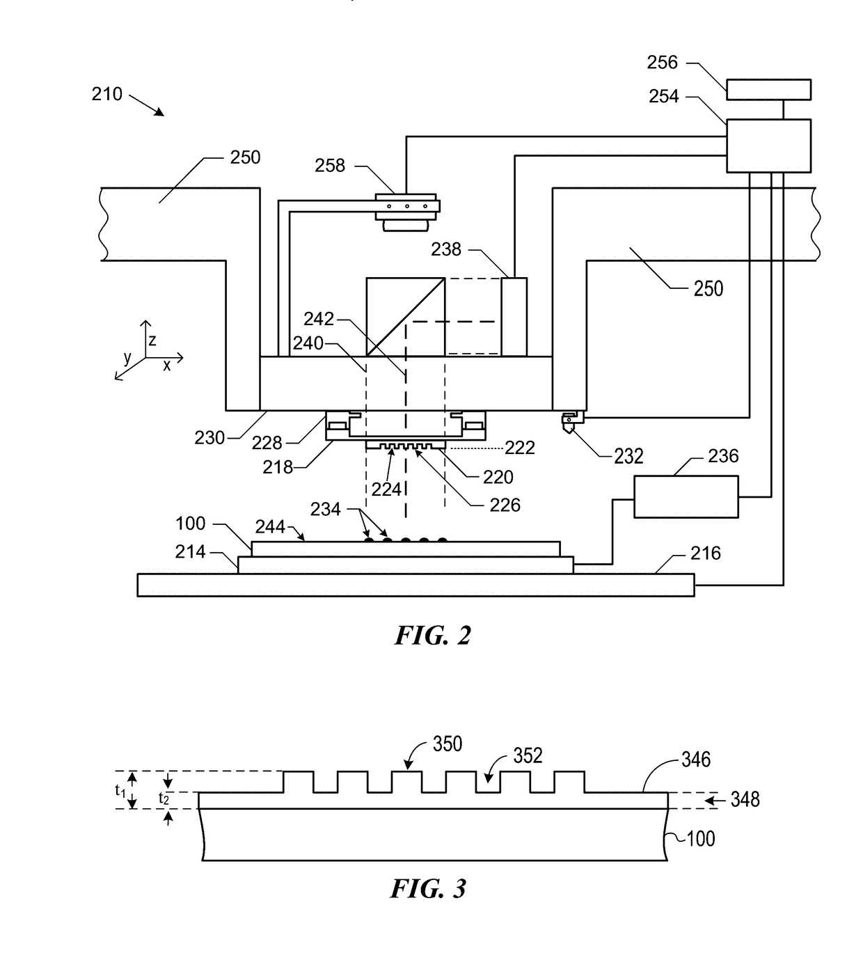
[0105] A method comprising:[0106]providing a workpiece within an imprint apparatus, wherein the workpiece includes a substrate and a formable material overlying the substrate; and[0107]contacting a template with the formable material within a partial field having a periphery, wherein contacting includes initially contacting the template with the formable material at a location spaced apart from the periphery of the partial field.

[0108]Embodiment 17. The method of Embodiment 16, wherein the imprint apparatus comprises a substrate holder including a chucking region, and providing the workpiece comprises placing the substrate over the chucking region.

[0109]Embodiment 18. The method of Embodiment 16 or 17, further comprising dispensing the formable material over the substrate, wherein different areas of the substrate have different areal densities of formable material.

[0110]Embodiment 19. The method of any one of Embodiments 16 to 18, further comprising spreading the formable material w...


PUM

PropertyMeasurementUnit
diameteraaaaaaaaaa
widthaaaaaaaaaa
widthaaaaaaaaaa

Abstract

In an embodiment, an imprint apparatus can include a substrate holder having a chucking region and a recessed support section; and a template holder, wherein the chucking region has more area as compared to a template region. In another embodiment, an imprint apparatus can include gas zones; and a gas controller that can be configured to adjust pressures within the gas zones to induce a convex curvature of a partial field of a workpiece used with the imprint apparatus. A method can include providing a workpiece within an imprint apparatus, wherein the workpiece includes a substrate and a formable material; and initially contacting a template with the formable material at a location spaced apart from the periphery of a partial field. In a particular embodiment, the method can further include modulating the substrate to form a convex shape contacting the template with the formable material.

Description

CROSS-REFERENCE TO RELATED APPLICATIONS[0001]The present application claims priority to U.S. Provisional Patent Application No. 62 / 266,455, filed Dec. 11, 2015, entitled “IMPRINT APPARATUS AND METHOD OF IMPRINTING A PARTIAL FIELD”, naming as inventors Mario Johannes Meissl et al., which is incorporated by reference herein in its entirety.FIELD OF THE DISCLOSURE[0002]The present disclosure relates to imprint apparatuses and methods of using the imprint apparatuses to imprint partial fields.RELATED ART[0003]Imprint apparatuses can be used to form patterns with small geometries (for example, less than 1000 nm) within a formable material. A full field or a partial field may be imprinted. A full field is a field in which all of an imprinting field of a template overlies all of a substrate and its corresponding overlying formable material. A partial field is a field in which only part and not all of an imprinting field of a template overlies the substrate or a portion of substrate where e...

Claims


Application Information

Patent Timeline
Patent Type & Authority Applications(United States)
IPC IPC(8): B29C59/02B29C35/02B29C37/00B29C59/00
CPCB29C59/021B29C37/0003B29C35/02B29C59/002B41K3/36G03F7/0002G03F7/707G03F7/70783G03F7/70825G03F7/70725G03F9/7057
Inventor MEISSL, MARIO JOHANNESZHANG, WEICHOI, BYUNG-JINYE, ZHENGMAO
Owner CANON KK
Why Eureka
Try Eureka