Neural recording system

Active Publication Date: 2014-06-26
RGT UNIV OF CALIFORNIA
View PDF19 Cites 9 Cited by
  • Summary
  • Abstract
  • Description
  • Claims
  • Application Information

AI Technical Summary

Benefits of technology

[0038]The neural amplifier structure is applicable for modern sub-100 nm CMOS technology, in which a low supply voltage, smaller output resistance, and larger leakage current emerge.
[0039]

Problems solved by technology

If the neural signal at the recording amplifier input is seriously atte

Method used


Image

  • Neural recording system
  • Neural recording system
  • Neural recording system

Examples


Embodiment Construction

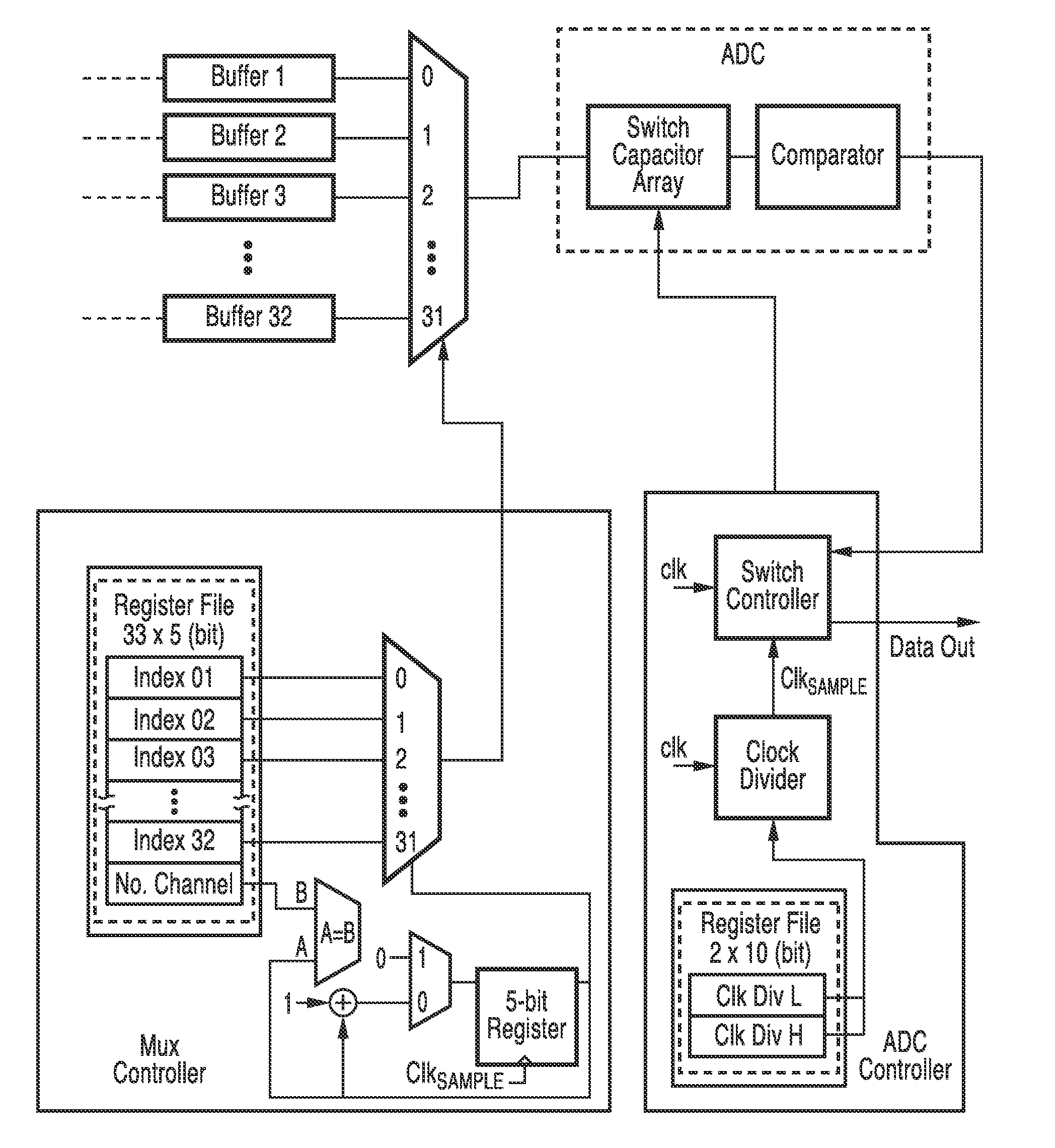
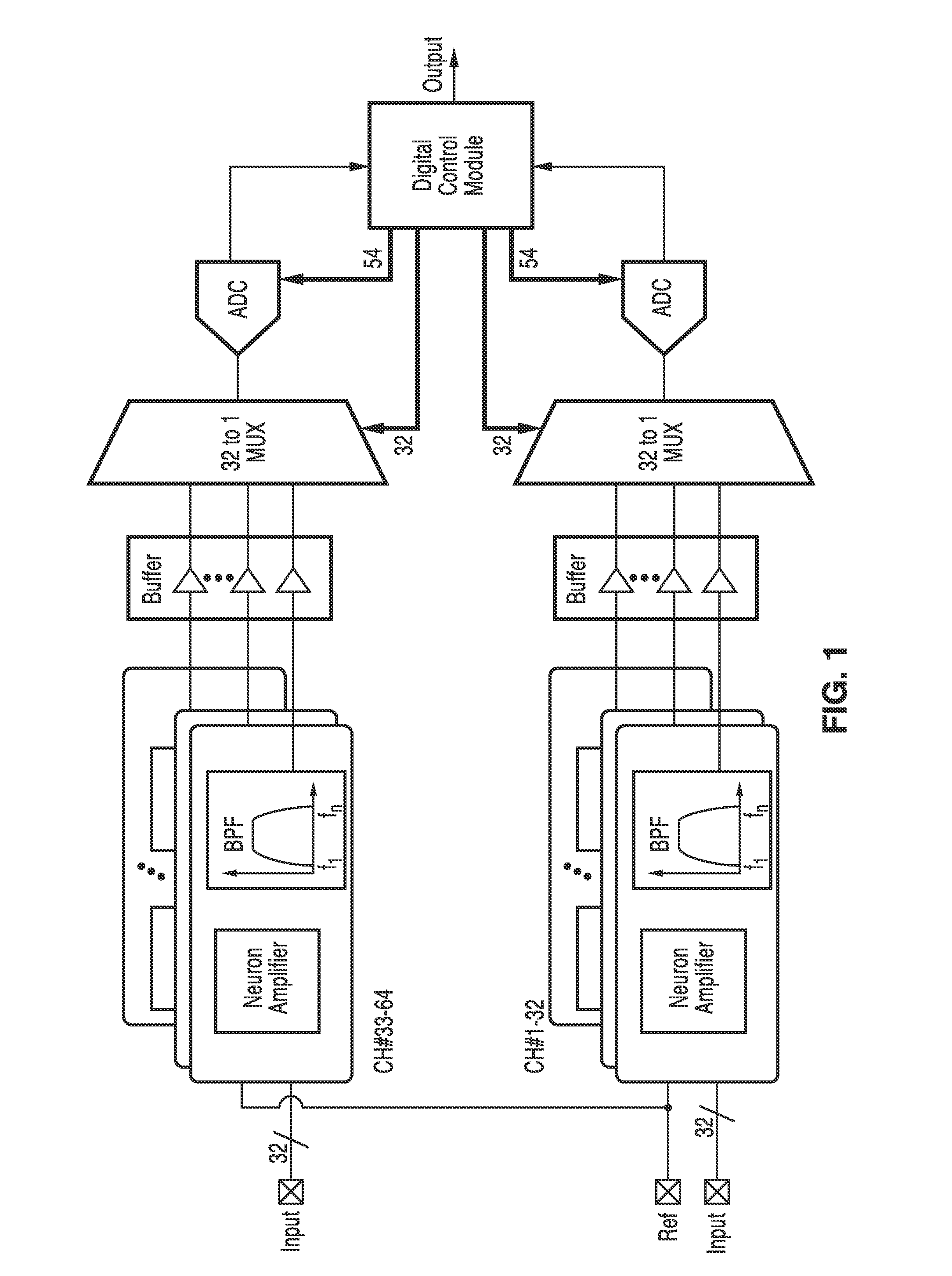
[0051]The overall system architecture is shown in FIG. 1. An exemplary embodiment of the 64-channel system includes two 32-channel recording units and a shared digital controller module (DCM). Each recording unit contains 32 recording channels, one 32-to-1 multiplexer, and an SAR ADC. Within each channel, the neuron amplifier first magnifies the infinitesimal neuron signal. A programmable gain and bandwidth filter is cascaded and configured based on the signal of interests. Buffer at each channel passes the filtered output to the multiplexer. The ADC then digitizes the signal with a sampling rate of 40 kS / s per channel and feeds the output to DCM for data serialization and performing channel-specific processing to identify multi-site components.

Circuit Design

[0052]Single Recording Channel

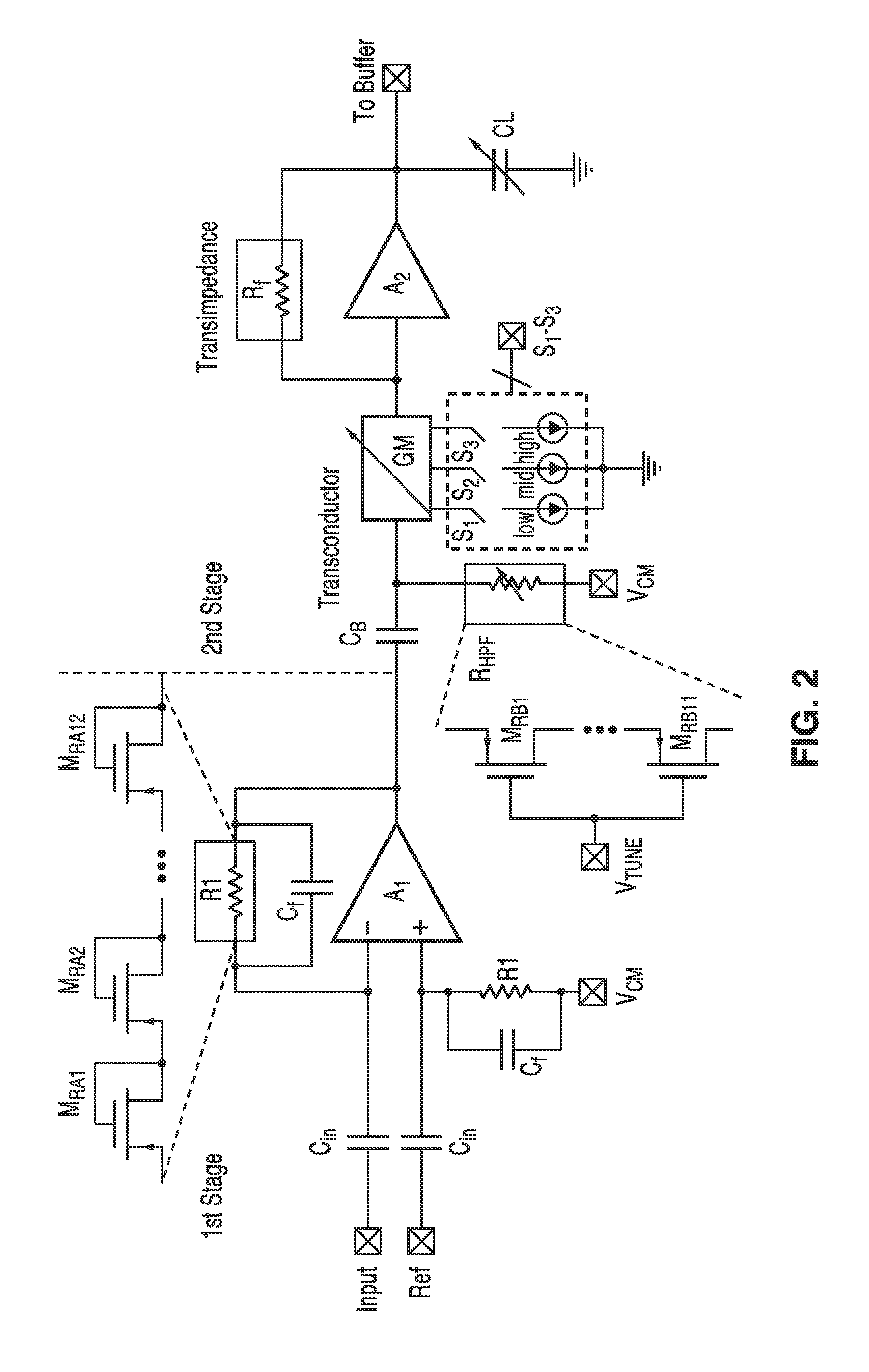
[0053]A schematic of one neuron recording channel is shown in FIG. 2. The first stage adopted an AC-coupled amplifier and provided a mid-band amplification of 39.6 dB. The high-pass cutoff frequency...


PUM


Abstract

A neuron recording system was provided. By using the gain-boosted topology, the amplifier input impedance can be increased while simultaneously reducing the noise. The system can be configured to record local field potentials (LFPs) and neuron spikes, respectively, with low-power consumption. With the flexible digital controller module (DCM), any subset of the recording channels can be activated for recording with independent sampling rate at each channel. A wireless interface to transmit recorded neuron data and an on-chip neuron processor to perform real-time signal processing can be incorporated in the system.

Description

CROSS-REFERENCE TO RELATED APPLICATIONS[0001]This application is a 35 U.S.C. §111(a) continuation of PCT international application number PCT / US2012 / 043173 filed on Jun. 19, 2012, incorporated herein by reference in its entirety, which is a nonprovisional of U.S. provisional patent application Ser. No. 61 / 571,098 filed on Jun. 20, 2011, incorporated herein by reference in its entirety. Priority is claimed to each of the foregoing applications.[0002]The above-referenced PCT international application was published as PCT International Publication No. WO 2012 / 177654 on Dec. 27, 2012 and republished on Jul. 4, 2013, which publications are incorporated herein by reference in their entireties.STATEMENT REGARDING FEDERALLY SPONSORED RESEARCH OR DEVELOPMENT[0003]Not ApplicableINCORPORATION-BY-REFERENCE OF COMPUTER PROGRAM APPENDIX[0004]Not ApplicableBACKGROUND OF THE INVENTION[0005]1. Field of the Invention[0006]This invention relates to methods, devices and system for recording of electric...

Claims


Application Information

Patent Timeline
IPC IPC(8): A61B5/04A61B5/0482A61B5/0478A61B5/375
CPCA61B5/7203A61B5/7225H03F3/45192H03F3/45475H03F3/45928H03F2200/165H03F2200/168H03F2200/171H03F2200/408H03F2203/45362H03F2203/45512H03F2203/45528H03F2203/45544H03F2203/45631H03F2203/45686H03F2203/45726A61B5/369A61B5/24A61B5/291A61B5/316A61B5/375
Inventor LO, YI-KAILIU, WENTAI
Owner RGT UNIV OF CALIFORNIA
Why Eureka
Try Eureka