High-speed laser array driver

a laser array and driver technology, applied in the field of high-speed laser array drivers, can solve the problems of degrading laser performance and changing laser characteristics during the operation of the laser, and achieve the effect of reducing power dissipation

Inactive Publication Date: 2002-05-30
OPTICAL COMM PRODS
View PDF10 Cites 32 Cited by
  • Summary
  • Abstract
  • Description
  • Claims
  • Application Information

AI Technical Summary

Benefits of technology

0008] In one embodiment of the present invention, a power down feature is pro

Problems solved by technology

Unfortunately, laser characteristics change during the operation of the laser.
In particular, as a laser such as a VCSEL is used to transmit optical

Method used


Image

  • High-speed laser array driver
  • High-speed laser array driver
  • High-speed laser array driver

Examples


Embodiment Construction

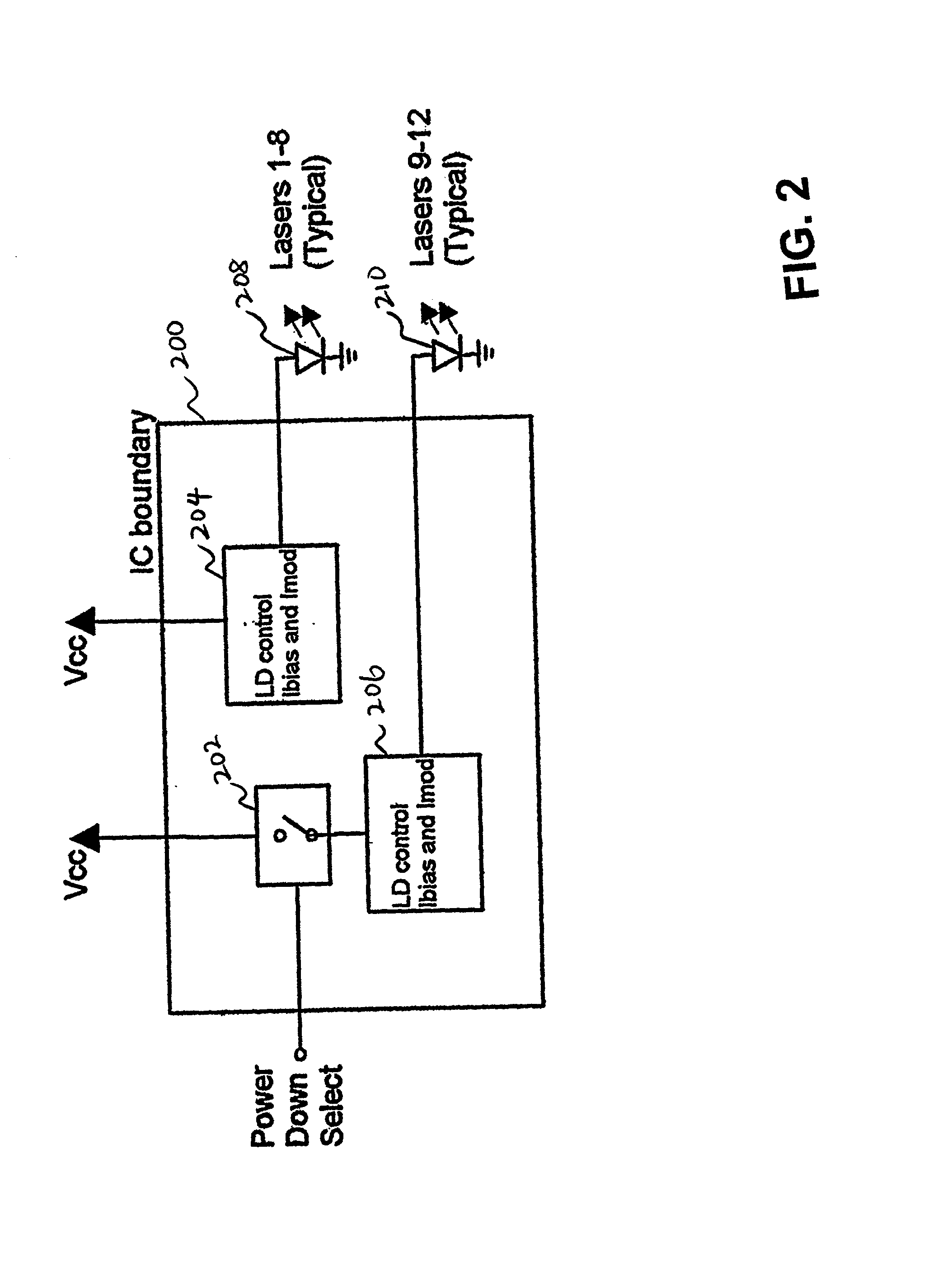
[0008] In one embodiment of the present invention, a power down feature is provided to disable one or more unused lasers so as to reduce power dissipation.

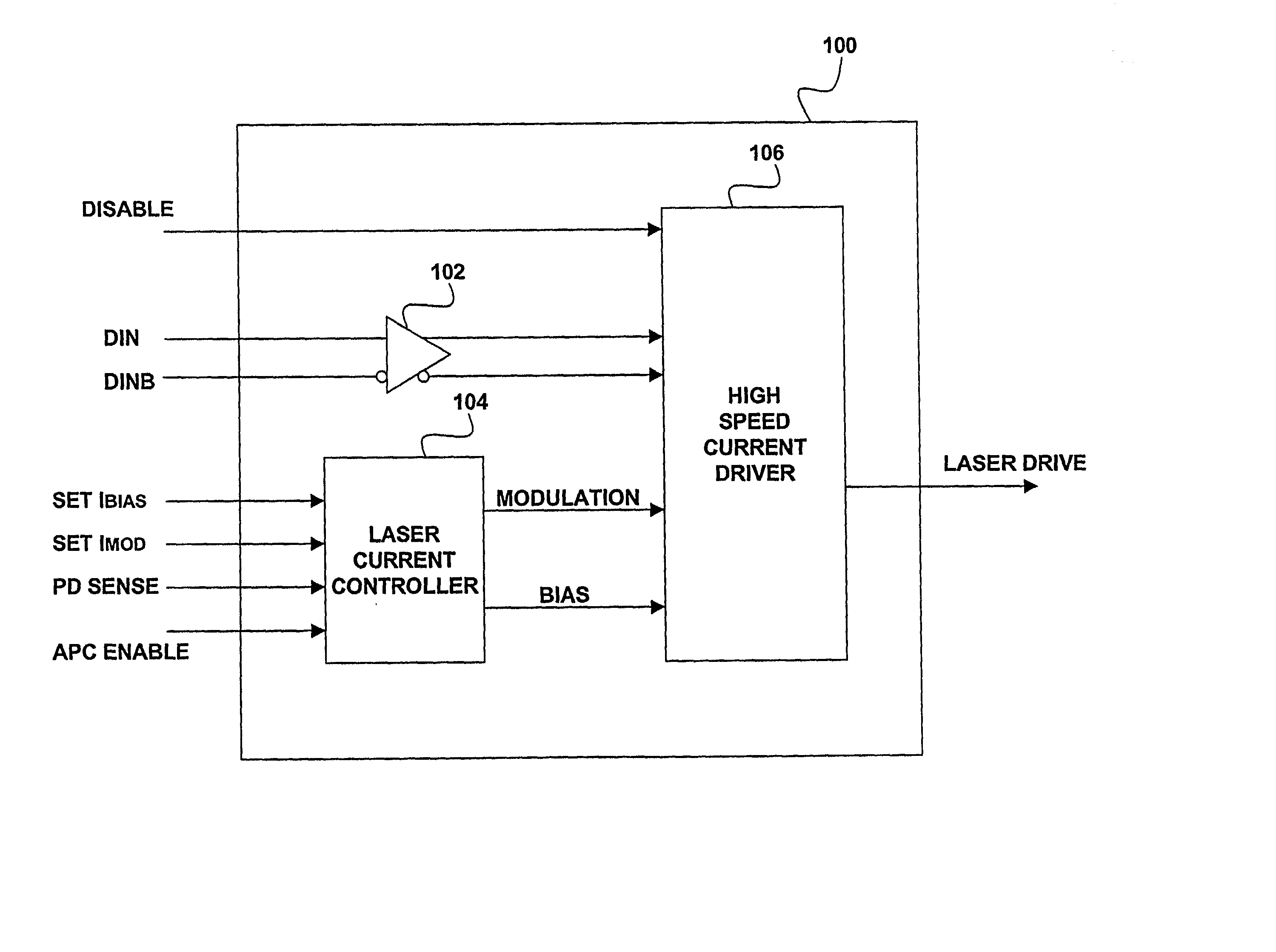
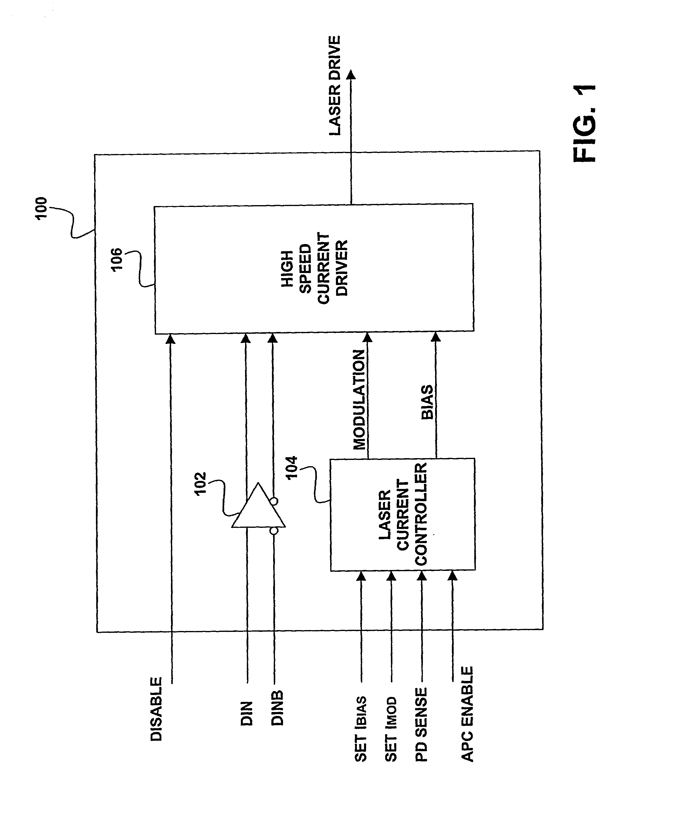
[0009] In another embodiment, a dual feedback system is used to provide feedback signals for the adjustment of modulation and bias currents delivered to a single laser or each laser in a laser array through the respective laser drivers. In this manner, the dual feedback system may be used to maintain average optical power and Optical Modulation Amplitude (OMA) within predetermined limit values. The feedback signals may be provided by one of the data lasers or by an additional control laser that operates at a lower frequency than the data lasers.

[0010] In yet another embodiment of the present invention, a transistor base leakage is used to emulate a large resistance element to result in a long time constant without the use of a large capacitor or large resistance.

[0011] In yet another embodiment of the present invention, a split po...


PUM


Abstract

A method and apparatus for driving lasers. An example laser driving system includes a laser current controller for providing a modulation signal and a bias signal. The modulation signal and bias signal is used by a plurality of high-speed current drivers that accept the modulation signal and the bias signal and produce a plurality of laser drive signals. The example system also has a disable input that disconnects power from a high-speed current driver when the high-speed current driver is not in use. The exemplary system develops the modulation and bias signals by feeding back a signal developed from detection of laser light from one of the lasers driven by the system. The laser may be a data laser or a control laser that is modulated by a signal having a lower frequency than the data lasers. If a control laser is used then the photodetector circuit used for feedback can have a lower frequency response because of the lower frequency of the control laser signal. The photodetector system may also employ a peak detector capacitor discharge circuit where a large capacitance is simulated by having the capacitor discharge through the base of a transistor have a current source in the emitter circuit.

Description

CROSS-REFERENCE TO RELATED APPLICATION(S)[0001] The present application claims the priority of U.S. Provisional Application No. 60 / 252,838 entitled "High-speed Laser Array Driver," filed Nov. 22, 2000, the contents of which are fully incorporated by reference herein.[0002] The present invention relates most generally to the field of optical transmission of information. More particularly, the present invention relates to an integrated circuit apparatus and method for driving lasers to maintain desired optical of lasers while reducing power consumption.BACKGROUND OF THE DISCLOSURE[0003] In the field of telecommunications, lasers such as vertical cavity surface emitting lasers (VCSELs) and other opto-electronic devices are commonly used for the transmission of information along optical fibers and the like. VCSELs, in particular are especially desirable in today's optical communication systems because they are efficient, small in size, readily assembled into arrays, and easy to manufact...

Claims


Application Information

Patent Timeline
IPC IPC(8): H01S3/00H01S5/042H01S5/062H01S5/0683H01S5/40
CPCH01S5/042H01S5/0427H01S5/4025H01S5/0683H01S5/06226
Inventor DIAZ, NELSONDUDEK, MICHAELEMBRY, CARL
Owner OPTICAL COMM PRODS
Why Eureka
Try Eureka