Supercharge Your Innovation With Domain-Expert AI Agents!

Tube fastening structure

a technology of fastening structure and tube, which is applied in the direction of sustainable buildings, lighting and heating apparatus, heating types, etc., can solve the problems of long time required for constructing the ground, risk of tube displacement, and need to fasten such types of tubes at a large time, so as to save mounting time, low cost, and high changeability

Active Publication Date: 2017-06-15
TAIWAN PAIHO LTD
View PDF15 Cites 2 Cited by
  • Summary
  • Abstract
  • Description
  • Claims
  • Application Information

AI Technical Summary

Benefits of technology

The present invention provides a way to fasten a tube in a floor heating system. This structure is effective, saves time, and is cost-efficient. Additionally, it is easy to change the position of the tube.

Problems solved by technology

However, if the tubes of the radiant floor heating system are secured by the above-mentioned method, since most of the tubes used in the radiant floor heating system are circulating (continuous) type loops, it needs lots of time to fasten such type of tubes and the metal wire for preventing the tubes from disconnecting during the mounting process.
And, since before performing the grouting process, the metal wire together with the tubes fastened thereon are not completely secured on the ground, there still exists a risk of displacement of the tubes.
Although such method can reduce a risk of displacement of the tubes during the securing process, yet the time necessary for constructing the ground is long and changeability for locations of the tubes is low.
In this regard, however, although such structure remains changeability for locations of the tubes, yet it is necessary to use the tubes having such special design, such that a cost for manufacturing the tubes is highly increased.

Method used


Image

  • Tube fastening structure
  • Tube fastening structure
  • Tube fastening structure

Examples


first embodiment

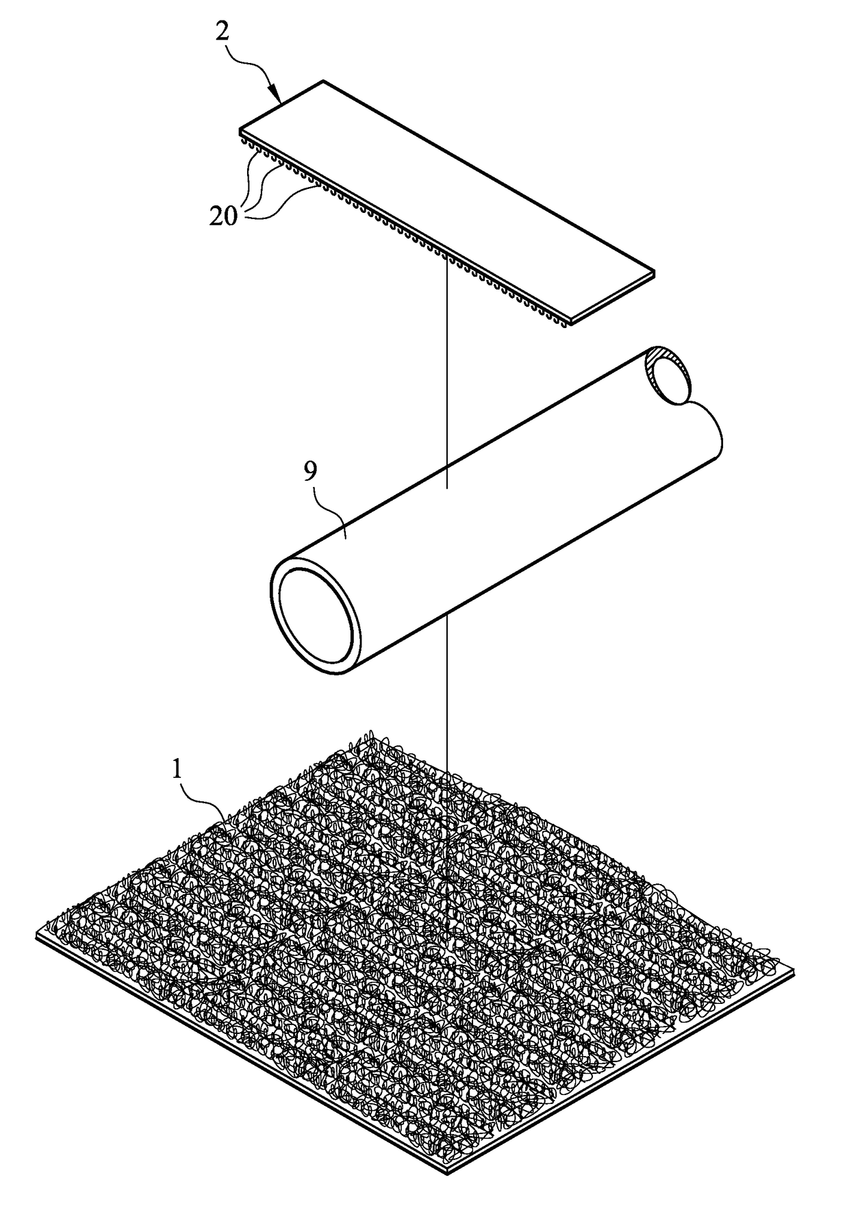
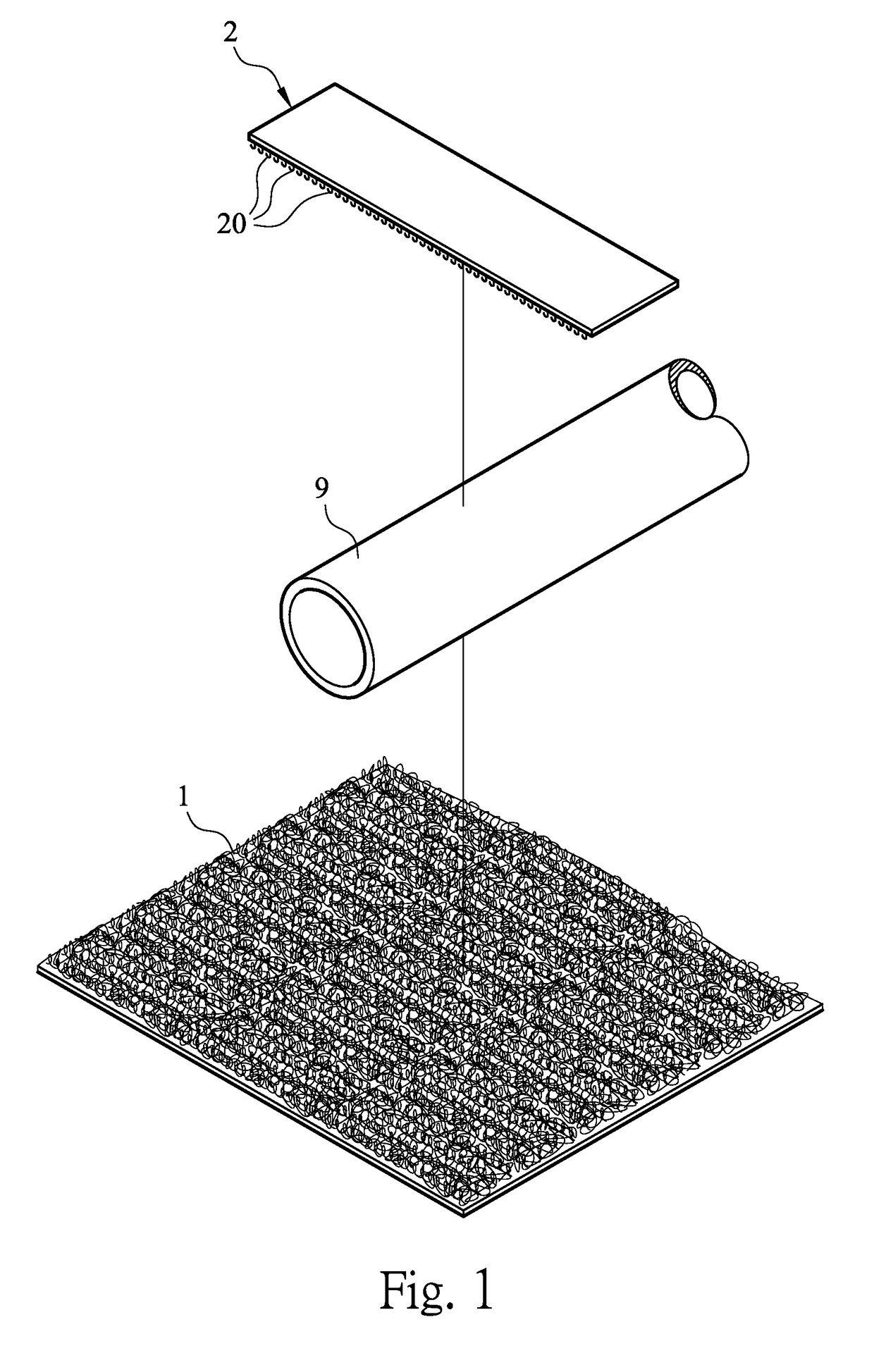
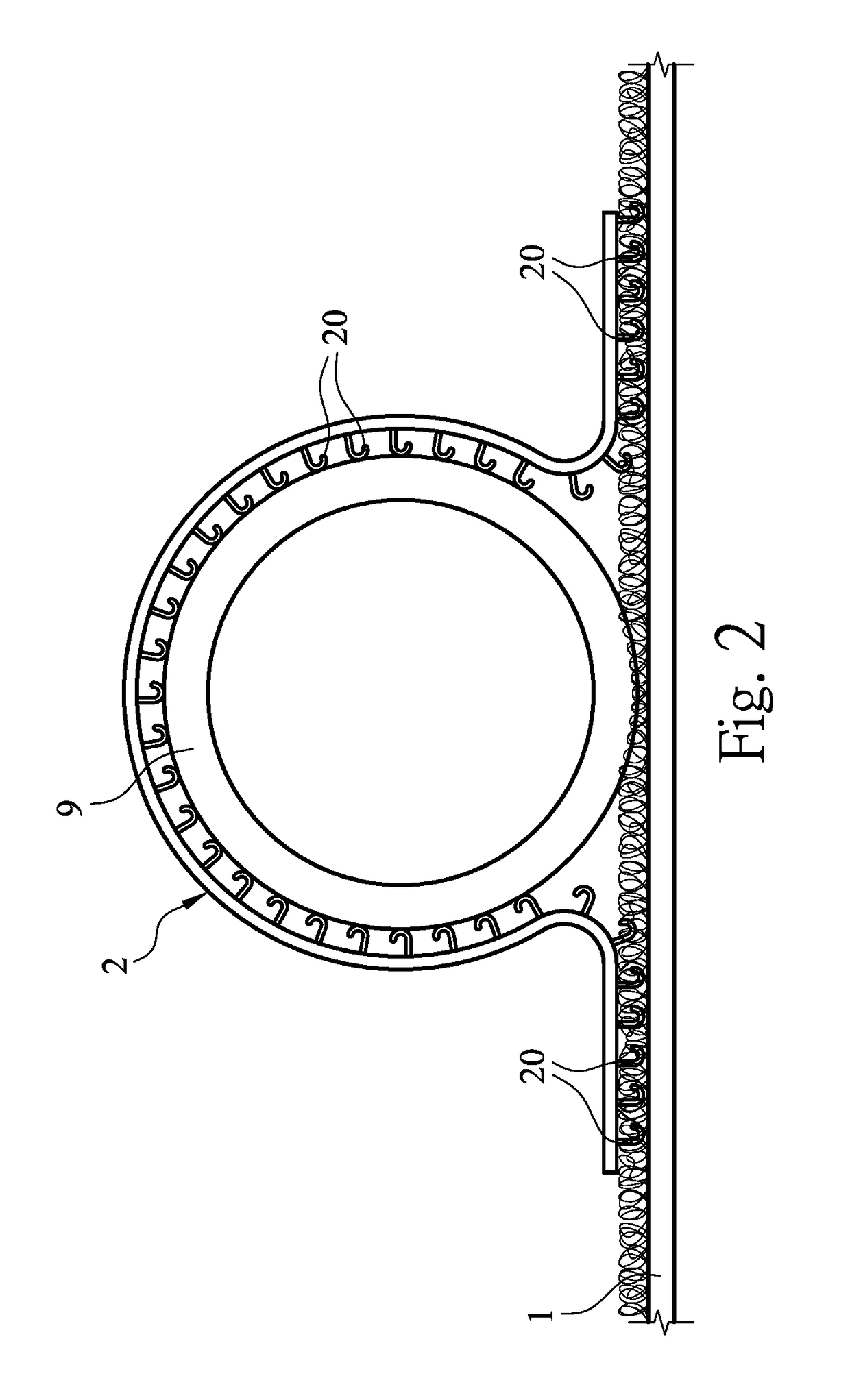
[0024]FIGS. 1 to 3 illustrate a tube fastening structure in accordance with the present invention.

[0025]As shown in FIG. 1, the tube fastening structure in accordance with the first embodiment of the present invention includes a bottom layer 1 and a fastening element 2. The bottom layer 1 has a surface of loop members. The fastening element 2 is provided with a plurality of hook members 20 on a surface (a first surface) thereof; and the plurality of hook members 20 are configured to be mechanically fastened to the surface of the loop members of the bottom layer 1.

[0026]Next, a case of using the tube fastening structure in accordance with the first embodiment of the present invention to fasten a tube 9 in a radiant floor heating system will be described. At beginning, the bottom layer 1 is disposed (fixed) on ground within a predetermined range where the radiant floor heating system is to be disposed, and the tube 9 to be disposed is placed on the bottom layer 1. Then, securely faste...

second embodiment

[0029]FIGS. 4 to 6 illustrate a tube fastening structure in accordance with the present invention.

[0030]As shown in FIG. 4, the tube fastening structure in accordance with the second embodiment of the present invention includes a bottom layer 1 and a fastening element 3. The bottom layer 1 has a surface of loop members. A first surface of the fastening element 3 is provided with a plurality of hook members 30, and a second surface of the fastening element 3, which is opposite to the first surface, is provided with loop members 35. The fastening element 3 includes a connecting body portion 300 and two wing portions 310 respectively on two opposite sides of the connecting body portion 300. Each of the two wing portions 310 has a fixed end connected to the connecting body portion 300, and a free end detachable from the connecting body portion 300 (referring to FIGS. 4 and 6). Specifically, the connection body portion 300 and the two wing portions 310 of the fastening element 3 are form...

third embodiment

[0033]FIGS. 7 and 8 illustrate a tube fastening structure in accordance with the present invention.

[0034]As shown in FIG. 7, the tube fastening structure in accordance with the third embodiment of the present invention includes a bottom layer 1, a seat body 4 and a fastening band 5. The bottom layer 1 is fixed on the ground and has a surface of loop members. A bottom surface of the seat body 4 has a plurality of hook members 40 which are configured to be mechanically fastened to the surface of the loop members of the bottom layer 1. The seat body 4 has an opening for passing through the tube 9 such that the tube 9 can be received on an inner arc surface 48 of the seat body 4 (referring to FIG. 8). The inner arc surface 48 is designed to be able to mate with an outer circumference surface of the tube 9 to be received thereon so as to achieve a better bearing effect. The fastening band 5 has a first section 51 and a second section 52 on an outer surface thereof in which the first sect...


PUM


Abstract

The present invention relates to a tube fastening structure for fastening a tube in a radiant floor heating system, the tube fastening structure comprising a bottom layer and at least one fastening element. The bottom layer is fixed on ground and has a surface of loop members. The fastening element has a plurality of hook members on a first surface thereof, and the plurality of hook members are configured to be mechanically fastened to the surface of the loop members of the bottom layer. After the tube is placed on the bottom layer, the fastening element is configured to fasten the tube in a manner of surrounding the tube by a mechanical fastening between the plurality of hook members and the surface of the loop members of the bottom layer.

Description

BACKGROUND OF INVENTION1. Field of Invention[0001]The present invention relates to a tube fastening structure for fastening a tube in a radiant floor heating system, in particular to a tube fastening structure for fastening a tube by a coordination of a surface of loop members and hook members.2. Related Prior Art[0002]In order to make people have a more comfortable indoor environment, some buildings may have a radiant floor heating system buried in ground for conditioning a temperature of the ground. Such radiant floor heating system operates mainly by tubes disposed in the ground.[0003]In the traditional radiant floor heating system, such as disclosed in U.S. Pat. No. 6,969,832B1, 7,145,112B1 or the like, in order to secure the tubes in the ground, it generally uses clips to fasten the tubes on a metal wire, laying the metal wire together with the tubes within a predetermined range on the ground, and performing grouting process to finish fastening of the tubes. However, if the tub...

Claims


Application Information

Patent Timeline
IPC IPC(8): F24D3/14F16L3/137F16B1/00F16L3/10
CPCF24D3/143F16L3/1058F16B2001/0028F16B1/00F16L3/137F16B5/12F16L3/04F16L3/1207F24D3/141F24D3/144Y02B30/00F16B2200/81
Inventor CHENG, ALLEN
Owner TAIWAN PAIHO LTD
Features
  • R&D
  • Intellectual Property
  • Life Sciences
  • Materials
  • Tech Scout
  • Unparalleled Data Quality
  • Higher Quality Content
  • 60% Fewer Hallucinations
Learn More