
Audio processing device, method of audio processing, storage medium, and electronic musical instrument

a technology of audio processing and audio, applied in the direction of instruments, electrotrophonic instruments, etc., can solve the problems of accumulating shifts and delay time not being completely synchronized, and achieve the effect of reducing the detected time differen

Active Publication Date: 2017-06-15
CASIO COMPUTER CO LTD
View PDF29 Cites 7 Cited by
  • Summary
  • Abstract
  • Description
  • Claims
  • Application Information

AI Technical Summary

Benefits of technology

The present invention is an audio processing device that can automatically play preset music and synchronize the output of audio effects with the playback of the music. It includes a first processor that cyclically counts a sampling clock and outputs an audio effect sound each time it reaches a certain value. A separate circuit unit or first processor detects the time difference between the count of the sampling clock and the count of the sequential clock, and adjusts the second count value for a subsequent cycle of counting in order to reduce the detected time difference and achieve synchronization of the output of the audio effect sound with the automatic play of the preset music over time.

Problems solved by technology

However, in conventional tempo synchronized delay features, the delay time is not actually completely synchronized with the tempo of the automatic performance due to discretization of delay time and / or the tempo with a clock or clocks, which are the minimum time units that can be handled in digital data processing.
However, if the delay feedback amount is large, the repeat count is high, or the feature is used to implement a sample looper that repeatedly plays back the same performance with the feedback set to 100%, the shift accumulates during each repetition until the error is magnified enough to be audible to the human ear.

Method used


Image

  • Audio processing device, method of audio processing, storage medium, and electronic musical instrument
  • Audio processing device, method of audio processing, storage medium, and electronic musical instrument
  • Audio processing device, method of audio processing, storage medium, and electronic musical instrument

Examples


Embodiment Construction

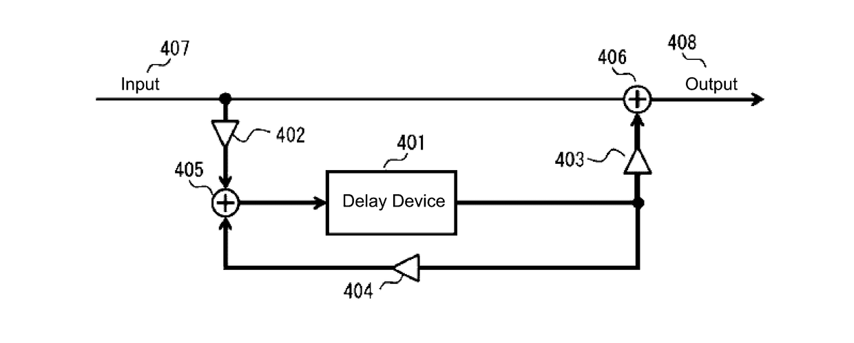
[0038]The inability to completely synchronize the delay time of a delay process (which is a type of audio effect process) to the tempo of an automatic performance (automatic play) in conventional technologies is due to the following reasons. First, the automatic performance control process that advances the automatic performance is typically executed by a central processing unit (CPU). The CPU implements a sequence clock counter that cyclically counts a hardware timer (that is, a system clock) from zero to a maximum sequence clock count that corresponds to a time obtained by dividing one beat of the specified tempo by a prescribed number (such as 480). This sequence clock counter issues a sequence clock interrupt each time the system clock count reaches the maximum sequence clock count. The CPU also executes the automatic performance control process, which advances the automatic performance in synchronization with these sequence clock interrupts. Meanwhile, the delay process is typi...


PUM


Abstract

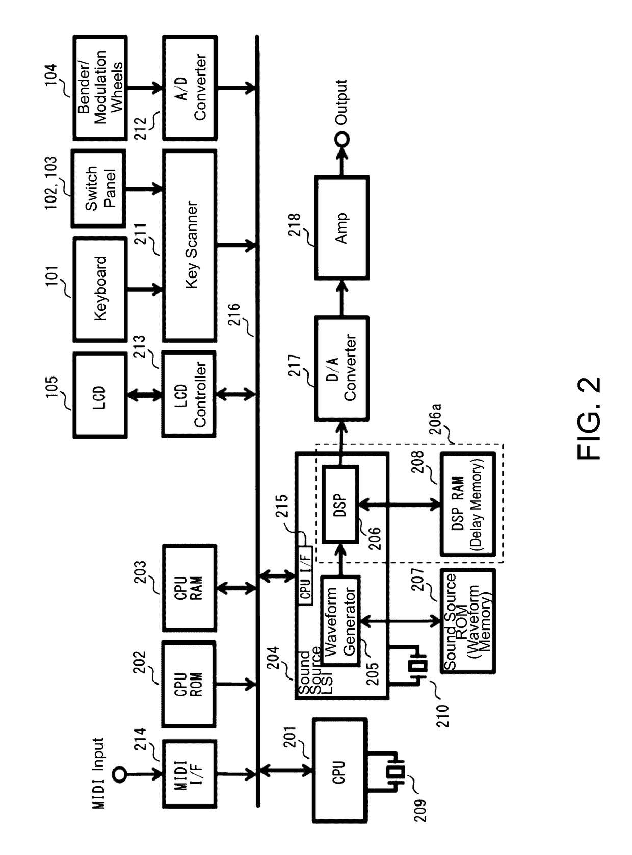
A delay time counter in a DSP cyclically counts a sampling clock from zero to a delay time sampling count and issues a delay time interrupt to a CPU each time the sampling clock count reaches the delay time sampling count. The CPU measures a time difference between each time the DSP issues the delay time interrupt and each time sequence clock interrupts occur a number of times corresponding to the delay time. Then, in order to reduce this time difference, the CPU increases or decreases a maximum count that is set to the sequence clock counter. Therefore, in the next delay process, the shift between the time by which the automatic performance is advanced by the CPU (which is equal to the delay time) and the timing of the delay process executed by the DSP (which is also equal in length to the delay time) will be corrected.

Description

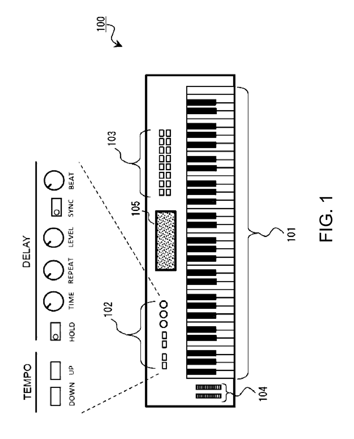
BACKGROUND OF THE INVENTION[0001]Technical Field[0002]The present invention relates to an audio processing device for synchronizing processes between two audio processors, a method of audio processing, a storage medium, and an electronic musical instrument that uses the audio processing device.[0003]Background Art[0004]In audio effects devices that are built into electronic musical instruments and have a delay feature for applying an echo effect to an input signal, there is a conventionally well-known technology known as tempo synchronization delay that automatically sets a delay time according to the tempo setting of an automatic performance (accompaniment, sequencer, arpeggio, or the like) of the electronic musical instrument such that the delay signal is synchronized with the rhythm of the music (the technology disclosed in Patent Document 1, for example). There are also well-known conventional technologies in which even if a song is currently being played, the content of an effe...

Claims


Application Information

Patent Timeline
Patent Type & Authority Applications(United States)
IPC IPC(8): G10H1/043G10H1/00
CPCG10H1/043G10H2210/391G10H2210/281G10H1/0008G10H2210/375G10H1/42G10H7/004G10H7/02G10H2210/201
Inventor SATO, HIROKI
Owner CASIO COMPUTER CO LTD
Learn More