
Electronic circuit breaker

a technology circuit breakers, applied in the direction of electronic switching, emergency protective arrangements for limiting excess voltage/current, electrical apparatus, etc., can solve the problems of increasing expenditure, increasing not only the driving outlay, and correspondingly large space requirements in the circuit of electronic circuit breakers, etc., to achieve cost-effective driving

Active Publication Date: 2017-06-15
ELLENBERGER POENSGEN
View PDF6 Cites 4 Cited by
  • Summary
  • Abstract
  • Description
  • Claims
  • Application Information

AI Technical Summary

Benefits of technology

The invention aims to create an electronic circuit breaker that works effectively without being too expensive or requiring a larger semiconductor switch. This will prevent the need for expensive driving equipment.

Problems solved by technology

A dimensioning of this type of employed semiconductor switch leads to increased expenditures, however, and a correspondingly large space requirement within the circuit of the electronic circuit breaker.
However, this increases not only the driving outlay.
Rather, PWM driving leads to problems in the case of inductive loads.

Method used


Image

  • Electronic circuit breaker
  • Electronic circuit breaker
  • Electronic circuit breaker

Examples


Embodiment Construction

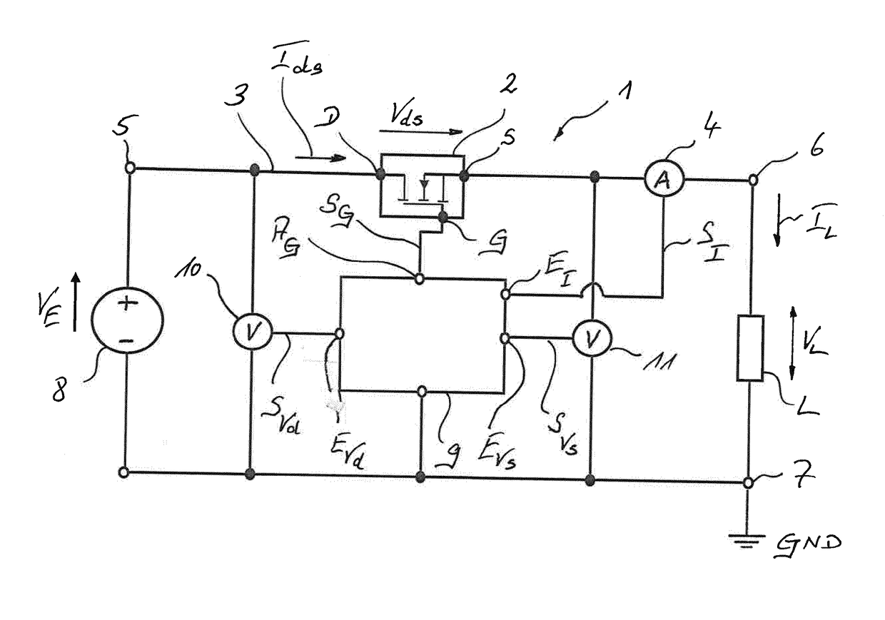
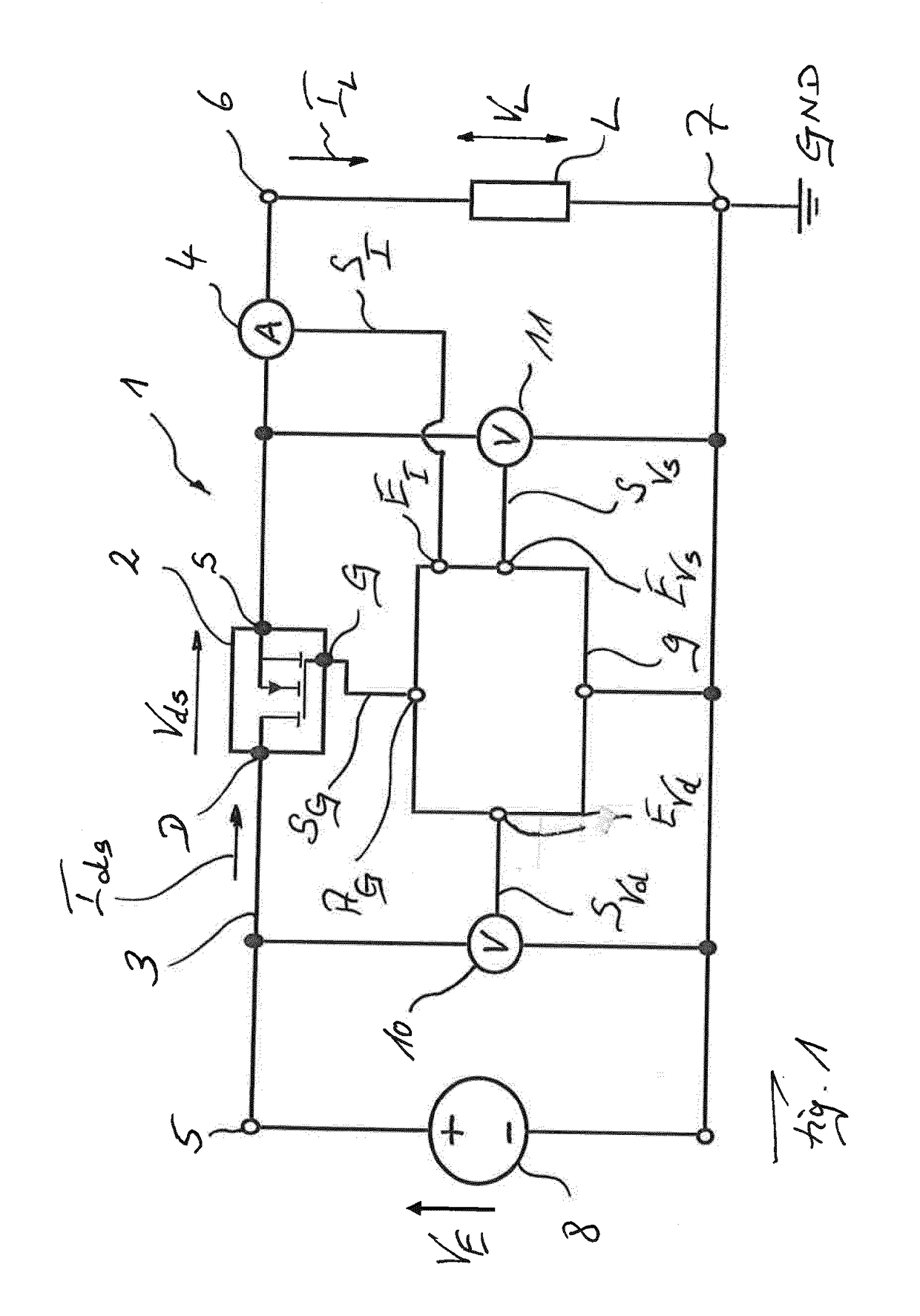
[0024]The schematically illustrated electronic circuit breaker 1 comprises a power transistor or semiconductor switch 2 in the form of a MOSFET, downstream of which a current sensor 4 is connected in a current path 3, namely, the positive path of circuit breaker 1. Current path 3 extends between an operating voltage connection or voltage input 5 and a positive load connection 6. The positive pole of a load L to be switched is connected to said load connection, whereas the negative pole of the load is to be connected to a corresponding negative load connection 7 of circuit breaker 1. Said connection 7 in the exemplary embodiment is taken to ground GND. The operating or input voltage VE generated by a current or voltage source of a power supply unit 8 in the form of, for example, a direct voltage with 24 V (DC) is applied at voltage input 5 of electronic circuit breaker 1.

[0025]In the case of connected voltage source 8 and connected load L, during operation of circuit breaker 1 a load...


PUM


Abstract

An electronic circuit breaker with a semiconductor switch, a drain connection and a source connection of the semiconductor switch being connected between a voltage input and a load output, and a gate connection of said semiconductor switch being connected to a control device which is supplied, at the input end, with a signal which represents the load current. The control device determines the drain-source voltage and, from this and from the detected load current, generates a control signal which is routed to the gate connection of the semiconductor switch and by means of which the power of the semiconductor switch is adjusted to less than or equal to a maximum power value.

Description

[0001]This nonprovisional application is a continuation of International Application No. PCT / EP2015 / 069693, which was filed on Aug. 27, 2015, and which claims priority to German Patent Application No. 10 2014 012 828.8, which was filed in Germany on Aug. 28, 2014, and which are both herein incorporated by reference.BACKGROUND OF THE INVENTION[0002]Field of the Invention[0003]The invention relates to an electronic circuit breaker with a semiconductor switch, the source connection and drain connection of which are connected between a voltage input and a load output, and the gate connection of which is connected to a control unit, which is supplied at the input end with a signal representing the load current.[0004]Description of the Background Art[0005]An electronic switch or circuit breaker of this type is known, for example, from DE 203 02 275U1. The electronic switch has a semiconductor switch in the form of a MOSFET (metal-oxide-semiconductor field-effect transistor), which is conn...

Claims


Application Information

Patent Timeline
Patent Type & Authority Applications(United States)
IPC IPC(8): H02H9/02H03K17/081H02H9/00
CPCH02H9/025H03K17/08104H02H9/001H03K17/082H03K17/0822
Inventor ASANZA MALDONADO, DIEGO FERNANDO
Owner ELLENBERGER POENSGEN
Learn More