Electronic circuit breaker

a circuit breaker and electronic technology, applied in the direction of electronic switching, emergency protective arrangements for limiting excess voltage/current, pulse techniques, etc., can solve problems such as circuit breakers, and achieve the effect of cost-effective driving

Active Publication Date: 2020-07-21
ELLENBERGER & POENSGEN GMBH
View PDF35 Cites 1 Cited by
  • Summary
  • Abstract
  • Description
  • Claims
  • Application Information

AI Technical Summary

Benefits of technology

[0008]It is therefore an object of the present invention to provide an electronic circuit breaker that operates as effectively as possible while avoiding the said disadvantages, wherein it is desirable to avoid an oversize semiconductor switch and the costly driving thereof. Also to be specified is a suitable method for controlling (driving) such an electronic circuit breaker, in particular even during a switch-on process of a load.
[0010]To this end, a voltage of the voltage-controlled current source circuit representing the output current, as the actual value, and the circuit's output voltage, are appropriately supplied to the control unit. If the difference value produced in or by the voltage-controlled current source circuit deviates from a threshold value in the event of an overload or short circuit or during a switch-on to a capacitive load, this state is detected by the control unit on the basis of the difference value, and preferably a current limiting takes place initially. In addition, the control unit sets the setpoint value of the output current such that the maximum power value of the semiconductor switch is not exceeded, which is to say the switch always operates within its safe operating area (safe operation area), taking its maximum power dissipation into account.

Problems solved by technology

Otherwise, if the output voltage does not rise, the semiconductor switch is blocked so that the electronic circuit breaker trips and disconnects the load from the current path.

Method used


Image

  • Electronic circuit breaker
  • Electronic circuit breaker
  • Electronic circuit breaker

Examples


Embodiment Construction

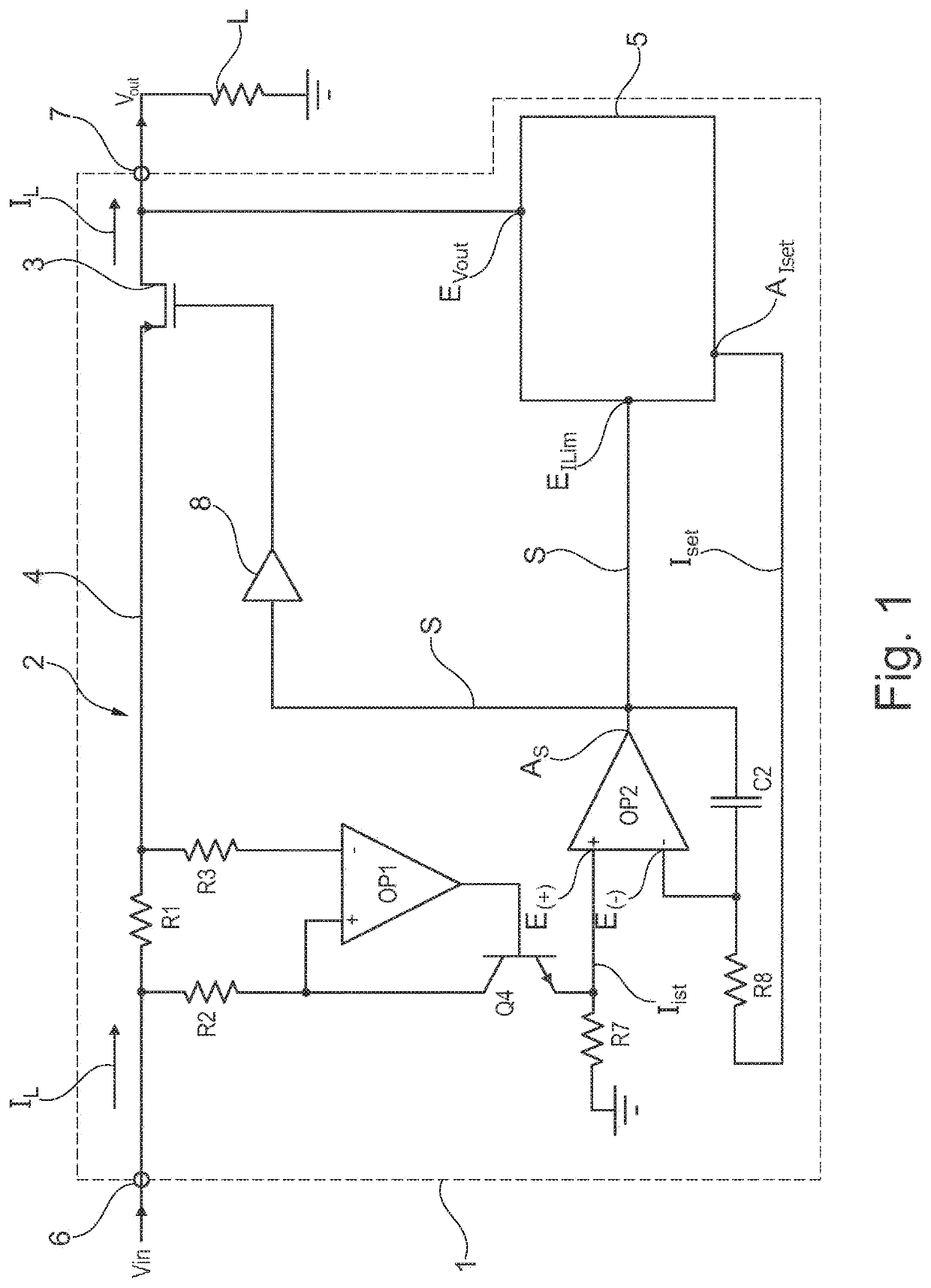
[0029]The schematically shown electronic circuit breaker 1 includes a voltage-controlled current source 2 with a power transistor or semiconductor switch 3 in a positive current path 4 and includes a control unit or control device 5, for example in the form of a microcontroller. The current path 4 extends between an operating voltage terminal or voltage input 6 and a (positive) load terminal or load output 7. To this is connected the positive pole of a load L that is to be switched, while the negative pole thereof is routed to earth or ground. The operating voltage or input voltage Vin, in the form of, e.g., a DC voltage at 24V (DC), is applied to the voltage input 6 of the electronic circuit breaker 1. The controllable semiconductor switch 3 in the exemplary embodiment is implemented by a so-called PMOS (p-channel MOSFET or PMOSFET), which is to say a metal oxide semiconductor field-effect transistor in which positively charged charge carriers (defect electrons) are used to conduct...


PUM

PropertyMeasurementUnit
voltageaaaaaaaaaa
voltageaaaaaaaaaa
voltageaaaaaaaaaa

Abstract

An electronic circuit breaker having a control unit and a controllable semiconductor switch which is connected in a current path between a voltage input and a load output, wherein the semiconductor switch is integrated into a voltage-controlled current source circuit, the output current of said current source circuit when the load is connected being adjusted by means of the control unit in such a way that the power of the semiconductor switch is lower than or equal to a maximum power value, and wherein the control unit outputs a setpoint value to the voltage-controlled current source circuit and receives a difference value from said voltage-controlled current source circuit, which difference value is formed from a deviation of an actual value, which represents the output current, from the setpoint value and is supplied to the semiconductor switch as a control signal for driving said semiconductor switch.

Description

[0001]This nonprovisional application is a continuation of International Application No. PCT / EP / 2016 / 068464, which was filed on Aug. 2, 2016, and which claims priority to German Patent Application No. 10 2015 219 545.7, which was filed in Germany on Oct. 8, 2015, and which are both herein incorporated by reference.BACKGROUND OF THE INVENTIONField of the Invention[0002]The present invention relates to an electronic circuit breaker having a control unit and having a controllable semiconductor switch connected in a current path between a voltage input and a load output. It additionally relates to a method for controlling an electronic circuit breaker of this nature.Description of the Background Art[0003]An electronic circuit breaker is described in DE 203 02 275 U1, for example. The electronic circuit breaker has a semiconductor switch in the form of a MOSFET (Metal Oxide Semiconductor Field Effect Transistor) that is connected in a current path between an operating voltage terminal an...

Claims


Application Information

Patent Timeline
Patent Type & Authority Patents(United States)
IPC IPC(8): H02H3/00H02H1/04H02H3/42H02H9/00H02H9/02H03K17/082H02H3/08
CPCH02H1/04H02H3/08H02H9/025H03K17/082H02H9/002H02H3/42H03K17/0822H03K2217/0054
Inventor ASANZA MALDONADO, DIEGO FERNANDO
Owner ELLENBERGER & POENSGEN GMBH
Why Eureka
Try Eureka