Electronic circuit breaker

Active Publication Date: 2018-08-09
ELLENBERGER POENSGEN
View PDF4 Cites 2 Cited by
  • Summary
  • Abstract
  • Description
  • Claims
  • Application Information

AI Technical Summary

Benefits of technology

[0008]It is therefore an object of the present invention to provide an electronic circuit breaker that operates as effectively as possible while avoiding the said disadvantages, wherein it is desirable to avoid an over

Problems solved by technology

Otherwise, if the output voltage does not rise, the semiconductor switch is blocked so t

Method used


Image

  • Electronic circuit breaker
  • Electronic circuit breaker
  • Electronic circuit breaker

Examples


Embodiment Construction

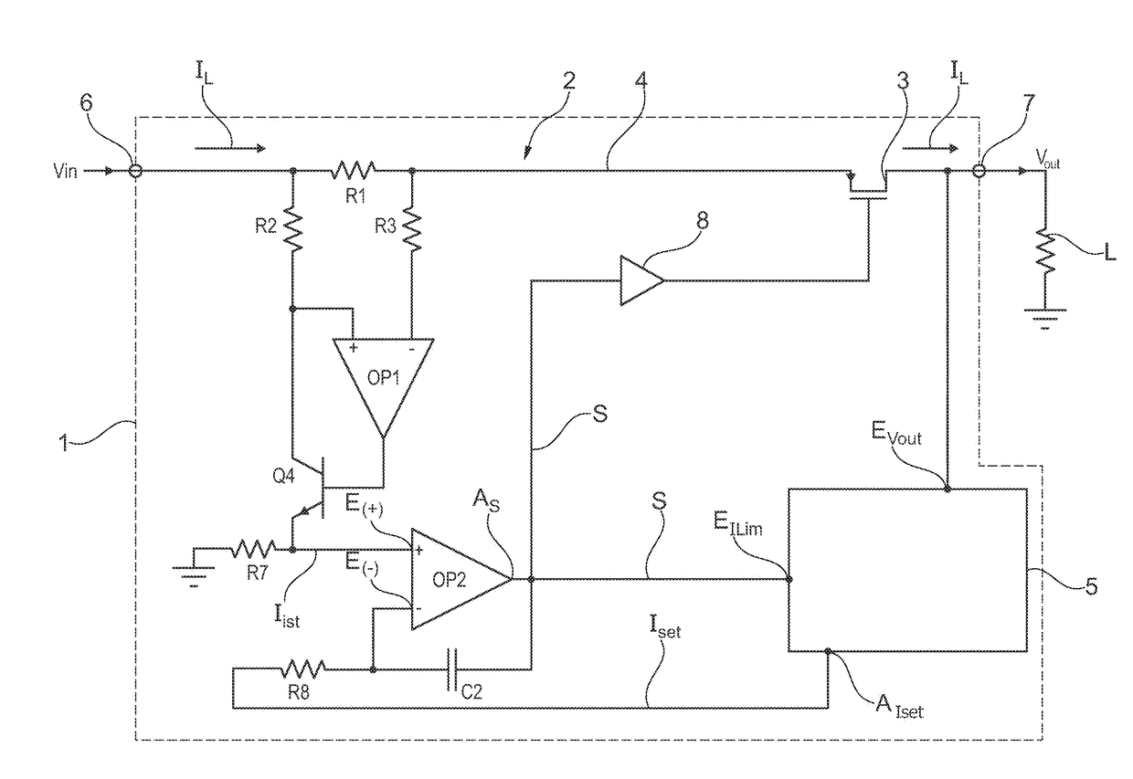
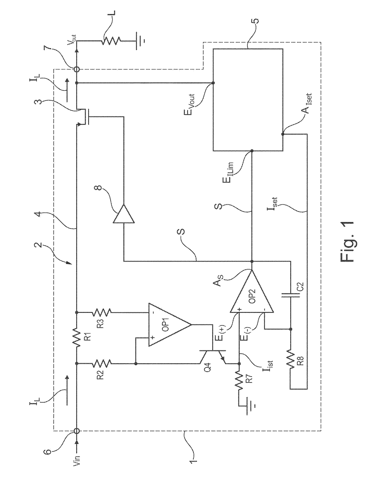
[0029]The schematically shown electronic circuit breaker 1 includes a voltage-controlled current source 2 with a power transistor or semiconductor switch 3 in a positive current path 4 and includes a control unit or control device 5, for example in the form of a microcontroller. The current path 4 extends between an operating voltage terminal or voltage input 6 and a (positive) load terminal or load output 7. To this is connected the positive pole of a load L that is to be switched, while the negative pole thereof is routed to earth or ground. The operating voltage or input voltage Vin, in the form of, e.g., a DC voltage at 24V (DC), is applied to the voltage input 6 of the electronic circuit breaker 1. The controllable semiconductor switch 3 in the exemplary embodiment is implemented by a so-called PMOS (p-channel MOSFET or PMOSFET), which is to say a metal oxide semiconductor field-effect transistor in which positively charged charge carriers (defect electrons) are used to conduct...


PUM


Abstract

An electronic circuit breaker having a control unit and a controllable semiconductor switch which is connected in a current path between a voltage input and a load output, wherein the semiconductor switch is integrated into a voltage-controlled current source circuit, the output current of said current source circuit when the load is connected being adjusted by means of the control unit in such a way that the power of the semiconductor switch is lower than or equal to a maximum power value, and wherein the control unit outputs a setpoint value to the voltage-controlled current source circuit and receives a difference value from said voltage-controlled current source circuit, which difference value is formed from a deviation of an actual value, which represents the output current, from the setpoint value and is supplied to the semiconductor switch as a control signal for driving said semiconductor switch.

Description

[0001]This nonprovisional application is a continuation of International Application No. PCT / EP / 2016 / 068464, which was filed on Aug. 2, 2016, and which claims priority to German Patent Application No. 10 2015 219 545.7, which was filed in Germany on Oct. 8, 2015, and which are both herein incorporated by reference.BACKGROUND OF THE INVENTIONField of the Invention[0002]The present invention relates to an electronic circuit breaker having a control unit and having a controllable semiconductor switch connected in a current path between a voltage input and a load output. It additionally relates to a method for controlling an electronic circuit breaker of this nature.Description of the Background Art[0003]An electronic circuit breaker is described in DE 203 02 275 U1, for example. The electronic circuit breaker has a semiconductor switch in the form of a MOSFET (Metal Oxide Semiconductor Field Effect Transistor) that is connected in a current path between an operating voltage terminal an...

Claims


Application Information

Patent Timeline
IPC IPC(8): H02H3/08H02H1/04H02H3/42H02H9/00H02H9/02H03K17/082
CPCH02H3/08H02H1/04H02H3/42H02H9/002H02H9/025H03K17/0822H03K17/082H03K2217/0054
Inventor ASANZA MALDONADO, DIEGO FERNANDO
Owner ELLENBERGER POENSGEN
Why Eureka
Try Eureka