Electrostatic Technology System And Process To Dehydrate Crude Oil In A Crude Oil Storage Tank Of A Floating Production Storage And Offloading Installation

a technology of electrostatic technology and crude oil, which is applied in the direction of liquid degasification, separation process, and wellbore/well accessories, etc., can solve the problem that the water cut of the inlet oil steam is limited to only about 30%, and achieve the effect of reducing the size and weight requirements

Active Publication Date: 2017-06-22
CAMERON SOLUTIONS
View PDF6 Cites 10 Cited by
  • Summary
  • Abstract
  • Description
  • Claims
  • Application Information

AI Technical Summary

Benefits of technology

[0018]Objectives of this invention include providing a system and process design that reduces the size and weight requirements of prior art FPSO process ...

Problems solved by technology

While this solution would save space and weight, the percentage...

Method used


Image

  • Electrostatic Technology System And Process To Dehydrate Crude Oil In A Crude Oil Storage Tank Of A Floating Production Storage And Offloading Installation
  • Electrostatic Technology System And Process To Dehydrate Crude Oil In A Crude Oil Storage Tank Of A Floating Production Storage And Offloading Installation
  • Electrostatic Technology System And Process To Dehydrate Crude Oil In A Crude Oil Storage Tank Of A Floating Production Storage And Offloading Installation

Examples


Embodiment Construction

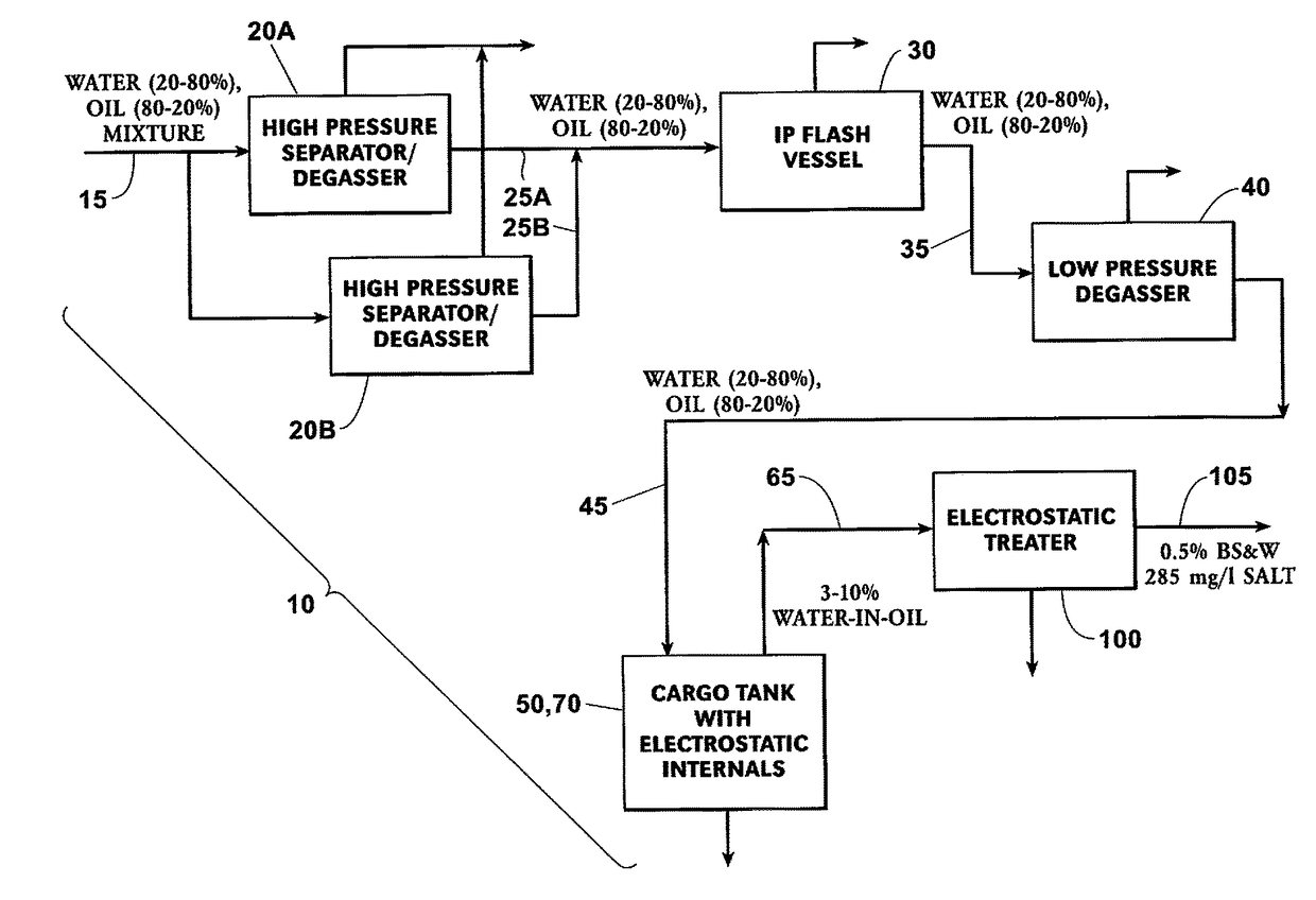
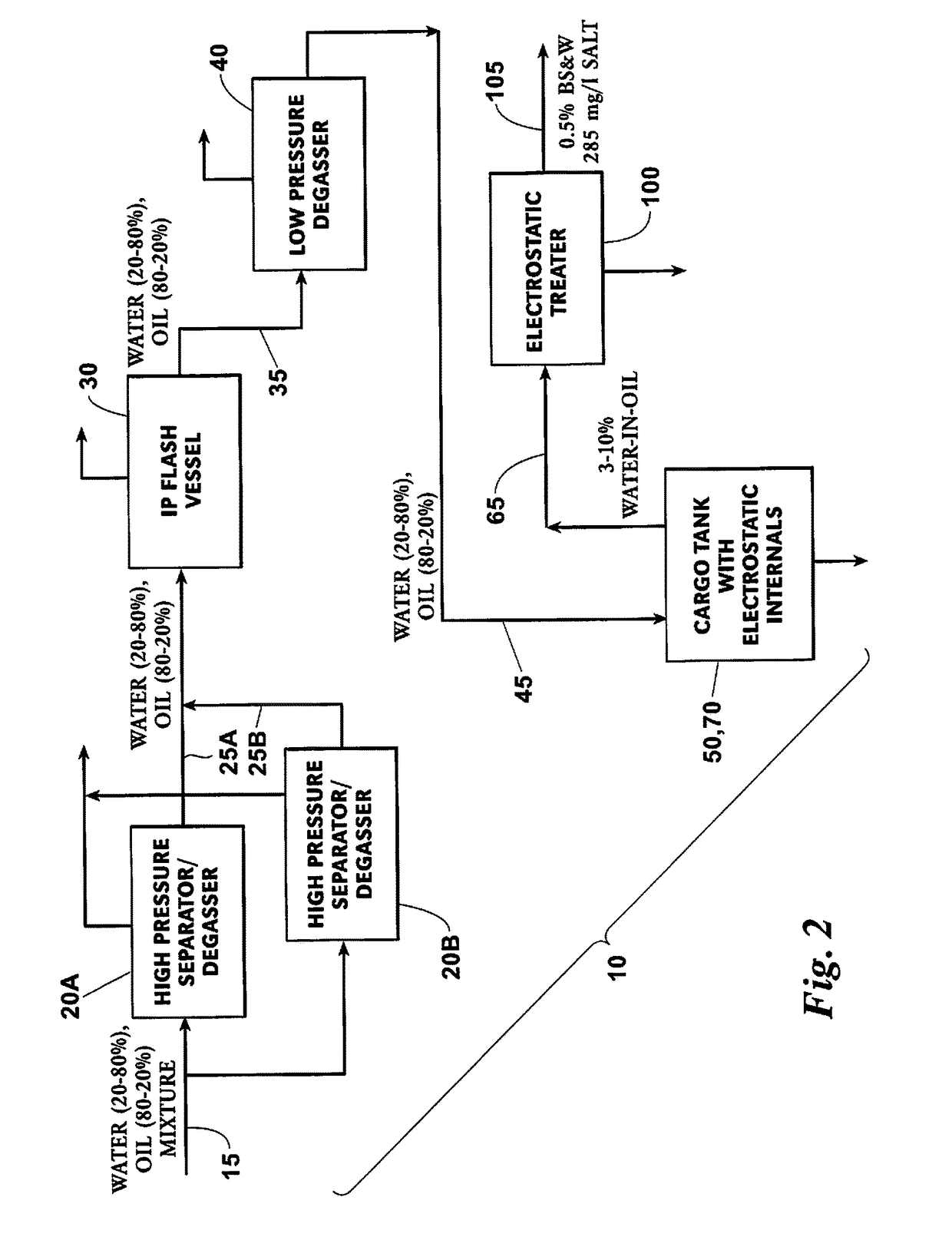
[0056]A preferred embodiment of a crude oil storage tank includes an electrostatic separator section having at least one set of electrostatic internals arranged to provide a treatment flow path oblique to a longitudinal centerline of the crude oil storage tank and isolated from a surrounding volume of the electrostatic separator section. The set of electrostatic internals is arranged for communication with an oil-and-water inlet section of the crude oil storage tank, a water outlet section of the crude oil storage tank, and an oil outlet section of the crude oil storage tank. An oil-and-water stream or mixture entering the set of electrostatic internals travels along the treatment flow path and is subjected to an electric field. The treatment flow path is in an upwardly direction toward the oil outlet section and in a downwardly opposite direction toward the water outlet section of the tank. Dehydrated oil exits the electrostatic internals and can reside outside of the electrostatic...


PUM

PropertyMeasurementUnit
Flow rateaaaaaaaaaa
Shapeaaaaaaaaaa

Abstract

A process train for a floating production storage and offloading installation includes a crude oil storage tank equipped with at least one set of electrostatic internals. The set of electrostatic internals are arranged to provide a treatment flow path within the crude oil storage tank oblique to a longitudinal centerline of the crude oil storage tank and through an electric field provided by the set of electrostatic internals. Employing these electrostatic internals within the tank permits an allowable inlet water content into the tank of up to 80%, significantly reducing the required topside processing equipment. The process and system also includes, upstream of the tank, two separator vessels arranged in parallel so each receives a portion of an incoming oil-and-water stream, a flash vessel arranged downstream of the two separator vessels, and a degasser vessel. Downstream of the crude oil storage tank is an electrostatic treater.

Description

BACKGROUND OF THE INVENTION[0001]This invention relates to systems, apparatuses, and methods used to dehydrate crude oil for storage in crude oil storage tanks of floating production storage and offloading (“FPSO”) installations. More specifically, the invention relates to a process train that includes electrostatic technology housed within the storage tank.[0002]Conventional topside oil separation trains on FPSO installations employ electrostatic separators to dehydrate crude oil for storage in crude oil storage tanks. These separators are part of the topside process train, and are typically large horizontal pressure vessels, which take up space and allowable weight.[0003]Undertaking the dehydration of the crude oil within the crude oil storage tank, by fitting the storage tank with conventional electrostatic internals, would eliminate the requirement for a separate electrostatic pressure vessel in the process train. While this solution would save space and weight, the percentage w...

Claims


Application Information

Patent Timeline
IPC IPC(8): C10G32/02B01D17/06B01D19/00C10G31/06
CPCC10G32/02B01D19/0036B01D17/06C10G31/06E21B43/34B03C11/00B03C2201/02C10G33/02
Inventor SPRENKEL, MARCUS D.SAMS, GARY W.MANDEWALKAR, S. PAVANKUMAR B.CAIRES FERNANDEZ, LUIS EDUARDO
Owner CAMERON SOLUTIONS
Why Eureka
Try Eureka