False start drain system with vertical header

a drain system and false start technology, applied in the direction of turbine/propulsion fuel valves, engine components, feed systems, etc., can solve the problems of local ignition, inadvertent extinguishing of flames in gas turbine engines, and failure of turbine engines to start properly, so as to reduce the mass flow of gases and increase heat transfer of hot gases

Active Publication Date: 2017-06-22
GENERAL ELECTRIC CO
View PDF15 Cites 4 Cited by
  • Summary
  • Abstract
  • Description
  • Claims
  • Application Information

AI Technical Summary

Benefits of technology

[0005]Another aspect of the disclosed technology relates to a combustor can drain system having a plurality of drain tubes routed directly to a v

Problems solved by technology

Sometimes the gas turbine engine fails to start properly, and/or the flame in the gas turbine engine is inadvertently extinguished.
However, if fuel becomes

Method used


Image

  • False start drain system with vertical header
  • False start drain system with vertical header
  • False start drain system with vertical header

Examples


Embodiment Construction

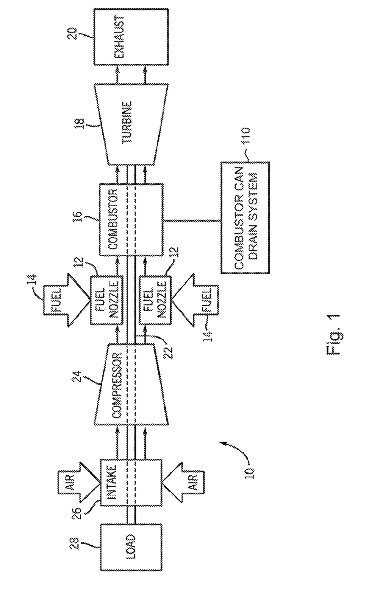
[0013]Referring to FIG. 1, a block diagram of an embodiment of a turbine system 10 is illustrated. As discussed in detail below, the disclosed turbine system 10 may employ a combustor can drain system 110. The turbine system 10 is capable of using liquid fuel and may be a dual fuel system capable of using liquid fuel and gas fuel, as those skilled in the art will understand.

[0014]As depicted, a plurality of nozzles 12 intakes a fuel supply 14, mixes the fuel with air, and distributes the air-fuel mixture to a combustor 16. The air-fuel mixture combusts in a chamber within combustor 16, thereby creating hot pressurized exhaust gases.

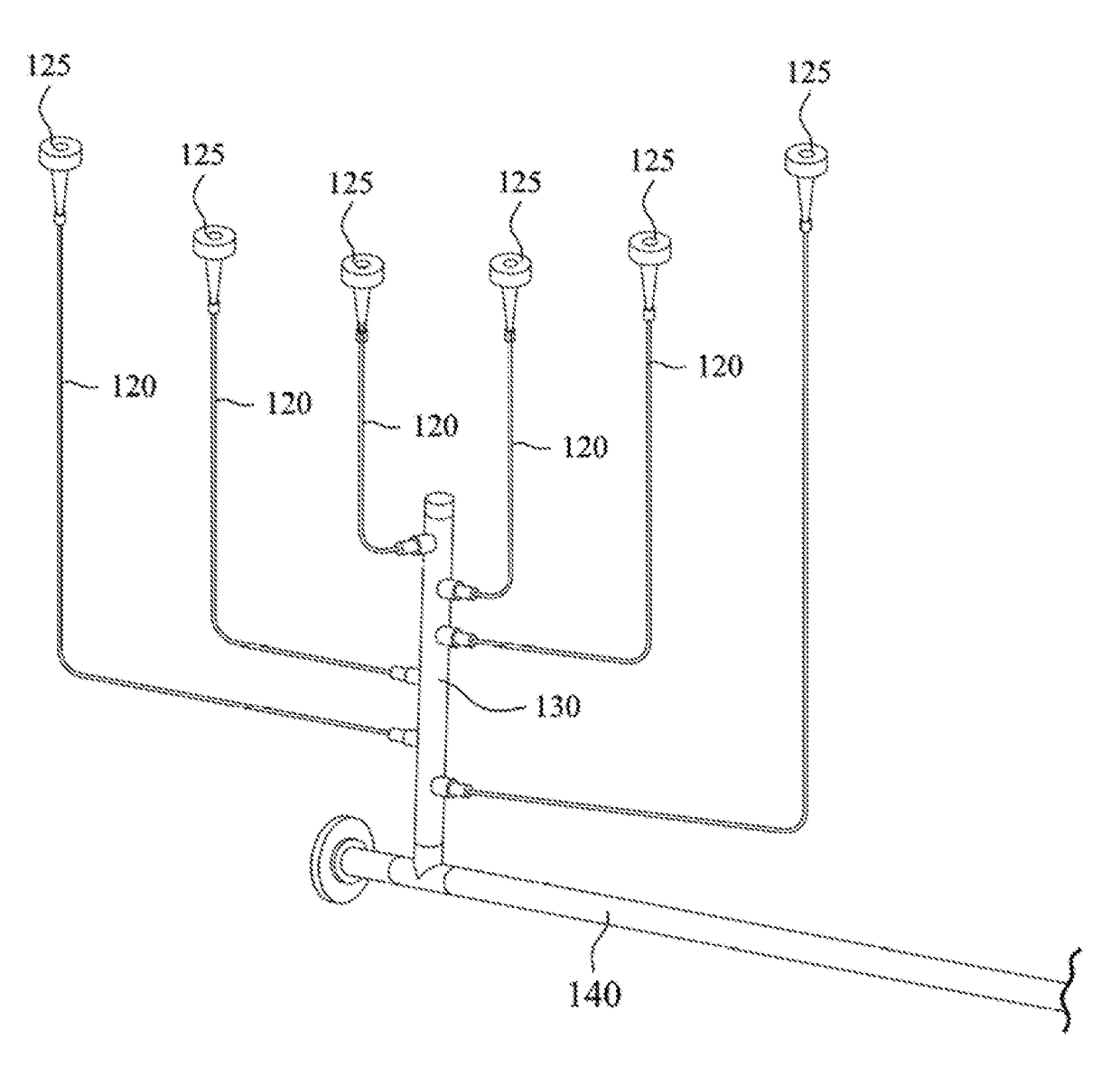
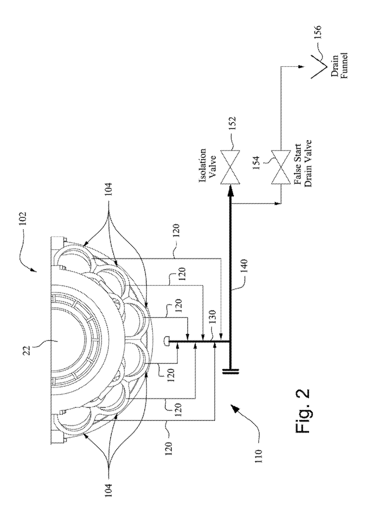
[0015]Combustor 16 directs the exhaust gases through a turbine 18 toward an exhaust outlet 20. As the exhaust gases pass through the turbine 18, the gases force one or more turbine blades to rotate a shaft 22 along an axis of the system 10. Referring to FIGS. 1 and 2, the combustor 16 may include a plurality of combustor cans 104 disposed annularly about ...


PUM


Abstract

A drain system for a combustor of a gas turbine includes a plurality of drain tubes, a vertical header connected to an end of each drain tube to receive a fluid flow therefrom, and a horizontal header downstream of the vertical header and in fluid communication therewith. Each drain tube has another end adapted to be connected to a respective combustor can of the gas turbine to drain liquid therefrom. The vertical header is disposed at an angle between 30° and 90° with a horizontal plane.

Description

FIELD OF THE INVENTION[0001]This invention relates generally to gas turbine engines, and more particularly to a combustor drain system for gas turbine engines.BACKGROUND OF THE INVENTION[0002]At least some known gas turbine engines include a compressor section, a combustor section, and at least one turbine section. The compressor compresses air, which is mixed with fuel and then channeled to the combustor. The mixture is then ignited generating hot combustion gases. The combustion gases are channeled to the turbine which extracts energy from the combustion gases for powering the compressor, as well as producing useful work to power a load, such as an electrical generator, or to propel an aircraft in flight.[0003]During a starting sequence, the engine is rotated to a predetermined speed, fuel is introduced, and an ignitor is energized. Sometimes the gas turbine engine fails to start properly, and / or the flame in the gas turbine engine is inadvertently extinguished. In either case, so...

Claims


Application Information

Patent Timeline
IPC IPC(8): F02C7/22F02C7/232
CPCF02C7/232F02C7/222
Inventor MAHADIK, DHIRAJ LAHUKANTRAJU, VENUGOPALA DURWASULADASOJI, ANIL KUMAR
Owner GENERAL ELECTRIC CO
Why Eureka
Try Eureka