Device for charging an energy store

a technology for charging energy and devices, applied in electric devices, electric vehicles, electrical apparatus, etc., can solve the problems of additional cost and complexity, limited charging process, direct coupling to batteries, etc., and achieve the effect of faster charging and higher charging power

Active Publication Date: 2017-06-22
FRAUNHOFER GESELLSCHAFT ZUR FOERDERUNG DER ANGEWANDTEN FORSCHUNG EV
View PDF0 Cites 20 Cited by
  • Summary
  • Abstract
  • Description
  • Claims
  • Application Information

AI Technical Summary

Benefits of technology

[0009]The invention is based on the finding that, when connecting a direct voltage source to two transducer circuits connected in parallel, a charging power of an energy store which is connected to the output of the transducer circuits can be increased. A higher charging power may be of advantage to be able to charge a car battery quicker, for example.
[0012]The double usage of a charger for AC or DC charging is of advantage since, by only very little additional expenditure, AC chargers may also be used for DC charging and, equally, a DC charger may also be used as an AC charger, thereby achieving considerable savings in cost and devices when compared to two separate systems for AC and DC charging. In addition, the current-carrying capacity and, thus, the power transferred can be increased considerably without considerable additional expenditure in the case of DC charging. Additionally, when using a motor converter comprising a DC / DC transducer for DC charging, a very high power can be transferred without having to integrate an additional charger in the vehicle.

Problems solved by technology

It is disadvantageous here that the charging process, with direct coupling to the battery, is limited in power due to the battery voltage and the limited current-carrying capacity of charge-plug devices available nowadays.
This disadvantage can be eliminated by using a DC / DC transducer within the vehicle, however, additional costs and complexity for elements result.

Method used


Image

  • Device for charging an energy store
  • Device for charging an energy store
  • Device for charging an energy store

Examples


Embodiment Construction

[0022]In the following description of the Figures, equal elements or elements of equal effect will be provided with equal reference numerals so that the description thereof in the different embodiments is mutually exchangeable.

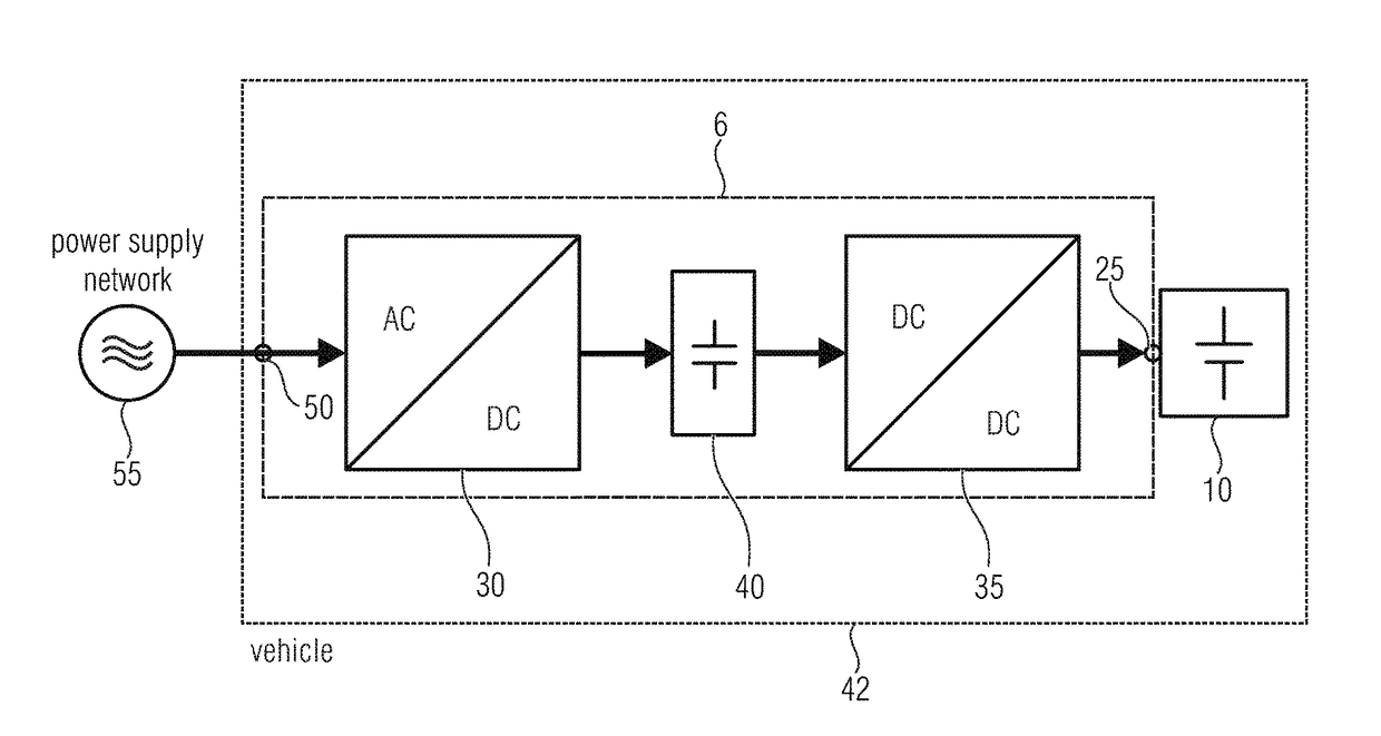
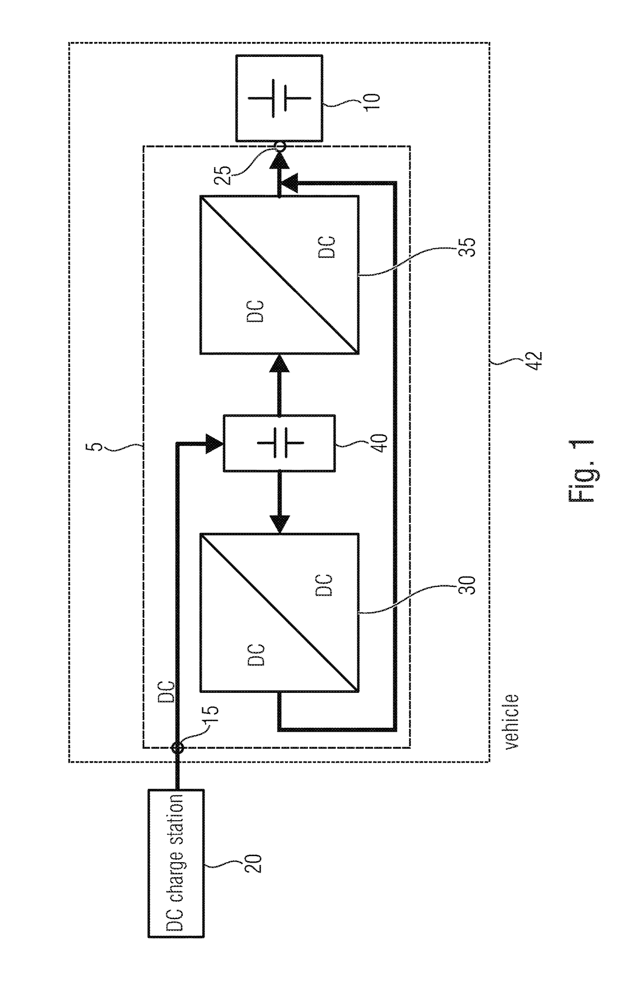
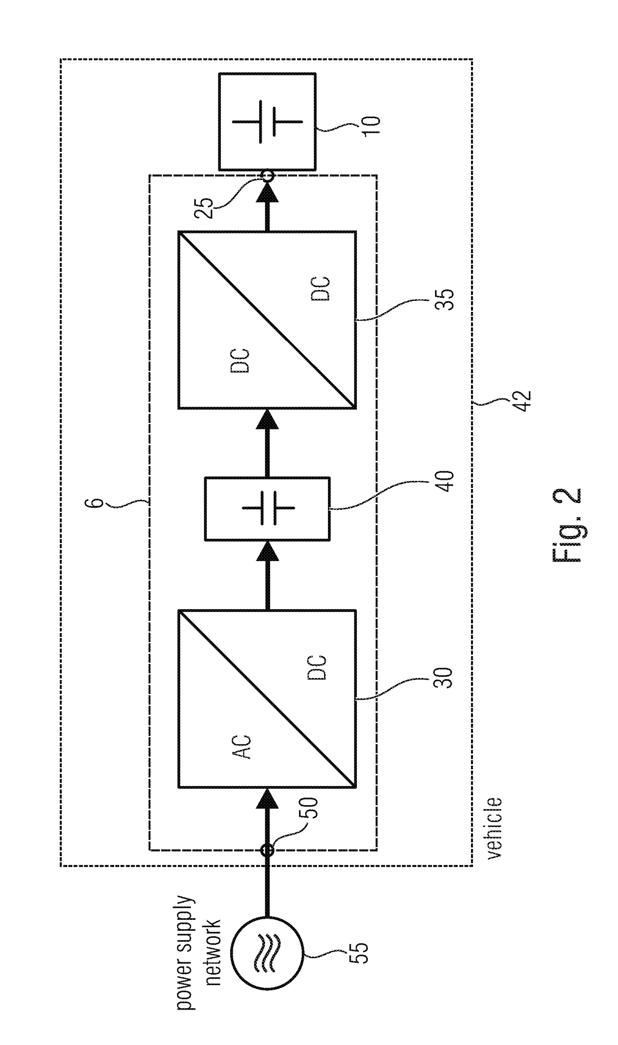
[0023]FIG. 1 shows a schematic block diagram of a charger 5 for charging an energy store 10 in accordance with an embodiment of the invention. A direct current source 20, like a DC charge station, is connected to a first terminal 15 of the device 5. In addition, the device 5 comprises a second terminal 25 to which the energy store 10 is connected. Furthermore, the charger 5 comprises two transducer circuits 30, 35 for converting an input voltage provided and an input current provided to an output direct voltage and an output direct current, and an intermediate connection circuit 40. In accordance with embodiments, the transducer circuits 30, 35 are DC / DC transducers configured to obtain a lower direct voltage and a higher direct current at the output of the ci...


PUM


Abstract

What is shown is a device for charging an energy store having a first terminal for connecting to a direct current source, a second terminal for connecting to the energy store, and a parallel connection between the first and second terminals, the parallel circuit having an intermediate connection circuit, a first transducer circuit for converting an input voltage and an input current to an output direct voltage and an output direct current, and a second transducer circuit.

Description

CROSS-REFERENCE TO RELATED APPLICATIONS[0001]This application is a continuation of copending International Application No. PCT / EP2015 / 070139, filed Sep. 3, 2015, which is incorporated herein by reference in its entirety, and additionally claims priority from German Application No. 10 2014 217 703.0, filed Sep. 4, 2014, which is also incorporated herein by reference in its entirety.BACKGROUND OF THE INVENTION[0002]The present invention relates to a device for charging an energy store. Embodiments describe a combined AC-DC quick charge system.[0003]If both ways of charging, that is AC and DC charging, are to be available optionally in a vehicle, this is ideally realized using a combined vehicle plug device allowing both AC and DC charging. A (single-phase or three-phase) AC charger is usually installed within the vehicle and, with optional DC charging, the DC charger is connected directly to the battery of the vehicle. It is disadvantageous here that the charging process, with direct ...

Claims


Application Information

Patent Timeline
Patent Type & Authority Applications(United States)
IPC IPC(8): H02J7/00B60L11/18H02J7/02
CPCH02J7/0055H02J7/022B60L2210/40H02J2007/0059B60L11/1816B60L2210/10B60L2210/30B60L2220/54Y02T10/7072Y02T90/14B60L53/14B60L53/22B60L53/24B60L53/11H02J2207/40H02J7/02H02J2207/20Y02T10/64Y02T10/72Y02T10/70Y02T90/12
Inventor TRITSCHLER, JOHANNESREICHERT, STEFAN
Owner FRAUNHOFER GESELLSCHAFT ZUR FOERDERUNG DER ANGEWANDTEN FORSCHUNG EV
Why Eureka
Try Eureka