
Motion sensor light, surveillance system and surveillance method

a technology of motion sensor and motion sensor light, which is applied in the direction of alarms, burglar alarms, instruments, etc., can solve the problems of increasing power consumption of illumination control devices, reducing illumination convenience, and reducing illumination convenience, so as to restrict the increase in power consumption

Active Publication Date: 2017-06-22
PANASONIC INTELLECTUAL PROPERTY MANAGEMENT CO LTD
View PDF21 Cites 14 Cited by
  • Summary
  • Abstract
  • Description
  • Claims
  • Application Information

AI Technical Summary

Benefits of technology

The present invention provides a motion sensor light that can keep the light on for a certain period of time and turn off quickly when no movement is detected. This reduces power consumption and prevents the light from being quickly turned off even when it is set to stay on for a certain period of time. This is achieved by a master device that saves operation conditions for the light and sends a lighting and lights-out command to the motion sensor light. The motion sensor light is designed to detect and respond to the movement of a moving object in its surroundings and can be used in a surveillance system. The technical effect of this invention is to provide an efficient and effective motion sensor light that saves power and can quickly turn off when no movement is detected.

Problems solved by technology

Accordingly, the convenience of illumination decreases, which means it is inconvenient.
Meanwhile, if the lighting maintaining duration is set as a longer period, the light is turned off only in a case where a person is not detected for a long period of time since the light is turned off in a case where motion of a person is not detected in the period of the lighting maintaining duration, and therefore power consumption of the illumination control device increases.
For example, in a case where the illumination control device operates by a battery for a reason of a place in which the illumination control device is installed, an increase in power consumption is a hindrance to use the illumination.

Method used


Image

  • Motion sensor light, surveillance system and surveillance method
  • Motion sensor light, surveillance system and surveillance method
  • Motion sensor light, surveillance system and surveillance method

Examples


Embodiment Construction

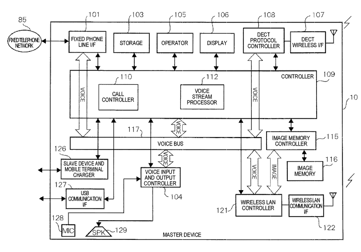
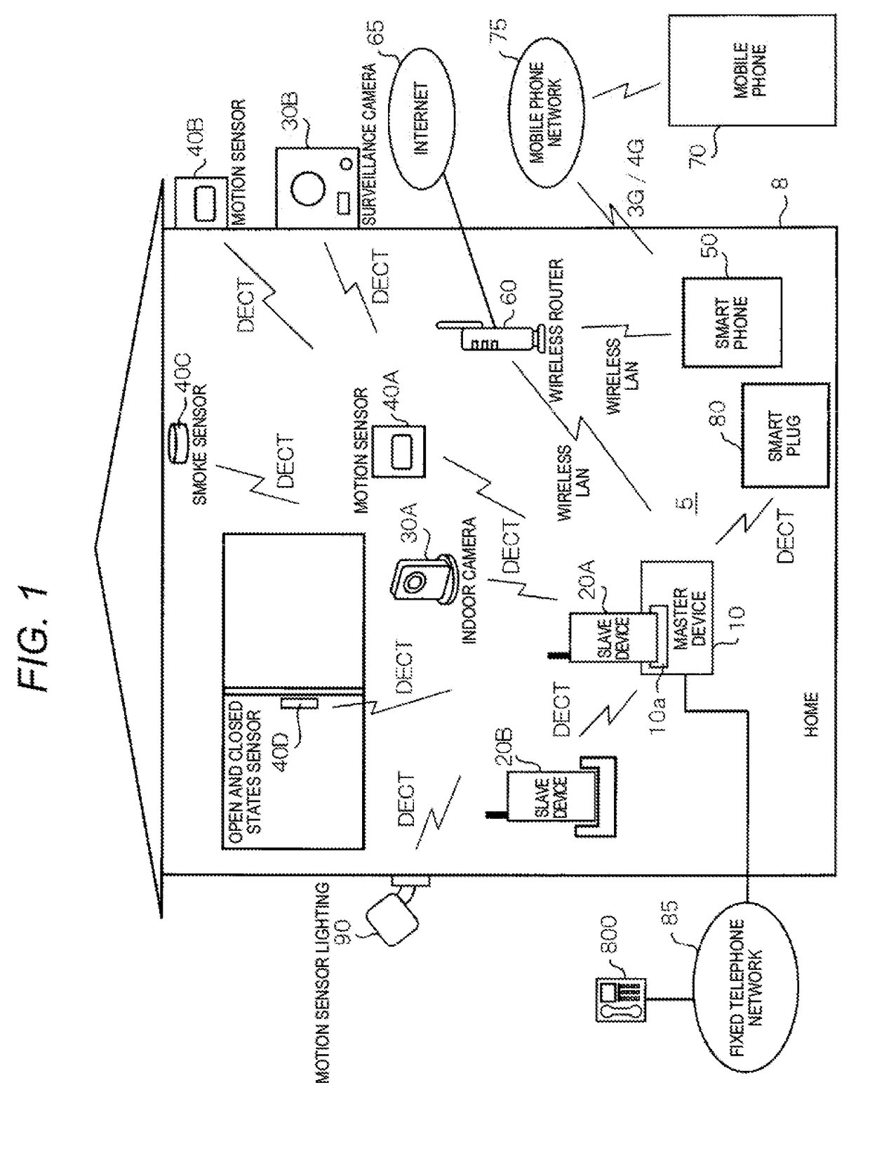
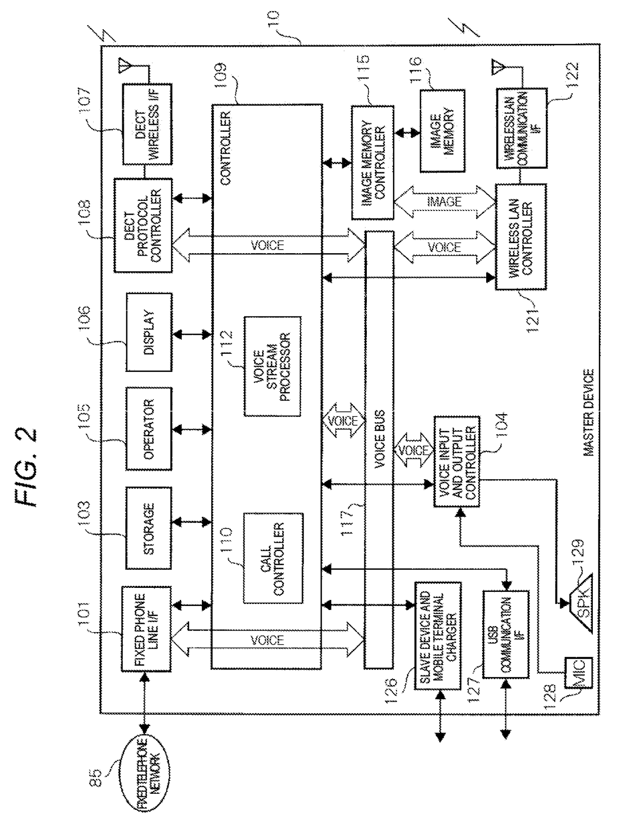
[0038]Hereinafter, an exemplary embodiment (hereinafter, referred to as the present exemplary embodiment) in which a motion sensor light according to the present disclosure is specifically disclosed will be described in detail with reference to appropriate drawings. However, in some cases, needlessly detailed descriptions will not be made. For example, in some cases, matters which are already known well will not be described in detail or practically the same configurations will not be described repeatedly. That is to avoid the following descriptions being needlessly long, and to promote understanding of those skilled in the art. The accompanying drawings and the following descriptions are provided to help those skilled in the art sufficiently understand the present disclosure. The drawing and the descriptions are not intended to limit the scope of the claims.

[0039]Hereinafter, the motion sensor light of the present exemplary embodiment will be described, for example, as a device tha...


PUM


Abstract

A motion sensor light turns on a light once a motion sensor detects movement of a person. The light illuminates a monitoring area once the light is turned on. The motion sensor light initiates measurement of lighting duration of the light. After then, the motion sensor light initiates measurement of lights-out delay duration in a case where the movement of a person is no longer detected, and acquires a set value of the lights-out delay duration according to the lighting duration set in advance. The motion sensor light turns off the light in a case where a measured value of the lights-out delay duration exceeds the set value of the lights-out delay duration and a measured value of the lighting duration of the light exceeds a set value of the lighting duration.

Description

BACKGROUND[0001]1. Technical Field[0002]The present disclosure relates to a motion sensor light that is turned on once movement of a moving object is detected.[0003]2. Description of the Related Art[0004]In the related art, a motion sensor light, which warns a moving object by being turned on once movement of the moving object (for example, a human) entered a monitoring area at night is detected, is known, for example, as a product for security purposes.[0005]In addition, for example, an illumination control device of Japanese Patent Unexamined Publication No. 2001-223092 is known as a related art that is related to an illumination device which detects movement of a moving object and then is turned on. The illumination control device of Japanese Patent Unexamined Publication No. 2001-223092 selects lighting maintaining duration of an illumination load based on the number of human body detection frequency within a predetermined period of time. This illumination control device is a de...

Claims


Application Information

Patent Timeline
IPC IPC(8): H05B37/02
CPCH05B37/0227H05B37/0272H05B37/0281H05B47/11H05B47/115H05B47/125H05B47/13H05B47/16H05B47/19Y02B20/40G08B13/18G08B13/19G08B13/19634G08B13/19695
Inventor TAKAHASHI, TAKESHI
Owner PANASONIC INTELLECTUAL PROPERTY MANAGEMENT CO LTD
Learn More