Lifting device on a lorry

Active Publication Date: 2017-06-29
VILLIGER PUBLIC SYST
View PDF18 Cites 3 Cited by
  • Summary
  • Abstract
  • Description
  • Claims
  • Application Information

AI Technical Summary

Benefits of technology

[0006]It is the object of the present invention to improve a lifting device of the above-mentioned type so that the construction of the lifting device is substantially more stable and has

Problems solved by technology

Furthermore, the construction of the suspension of the boom at the upper end of the telescopically extensible support is relatively weak.
Po

Method used


Image

  • Lifting device on a lorry
  • Lifting device on a lorry
  • Lifting device on a lorry

Examples


Embodiment Construction

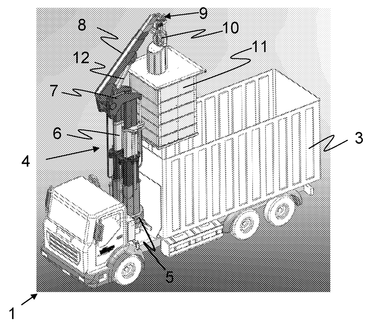
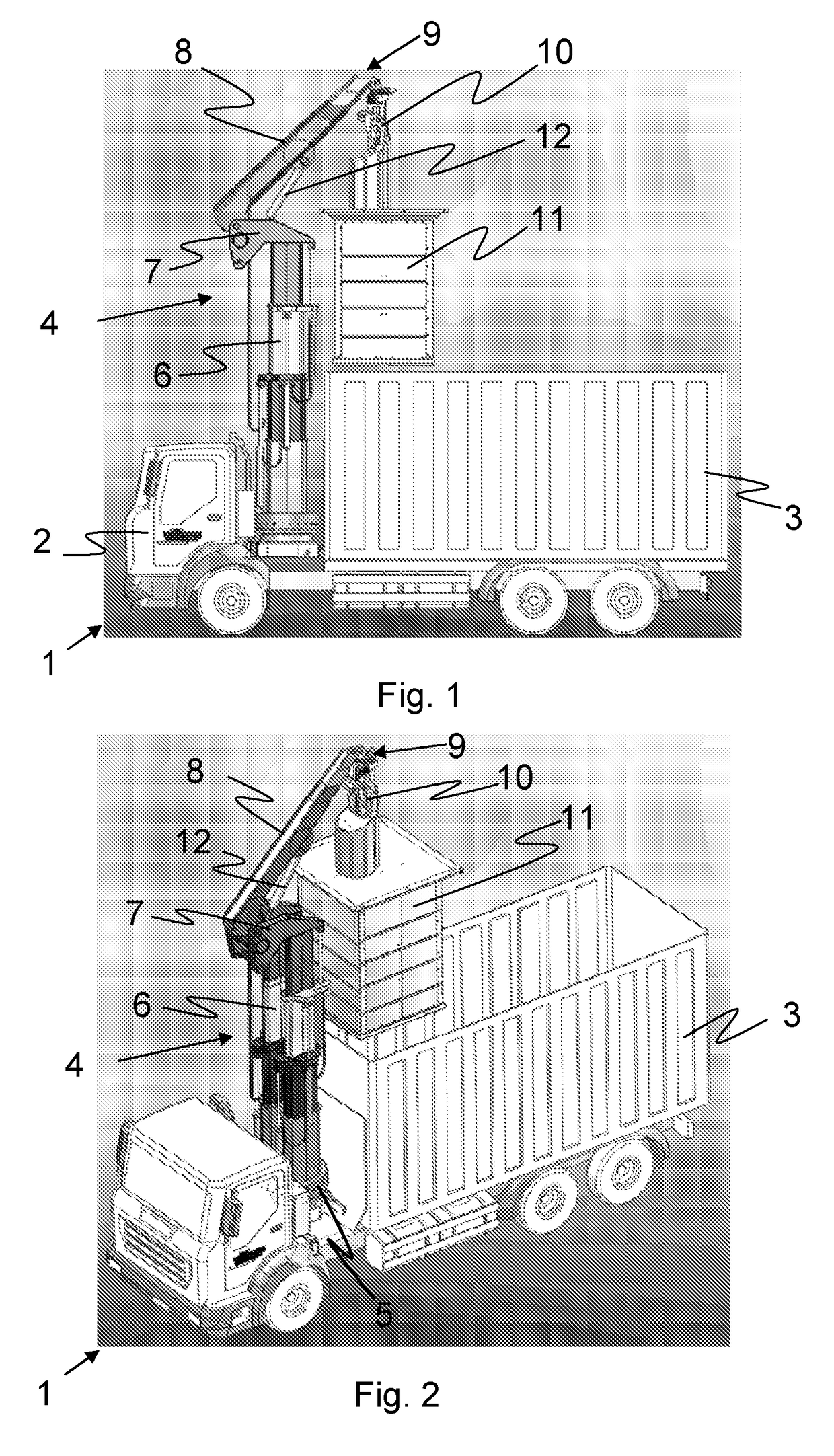
[0026]FIGS. 1 and 2 show a heavy goods vehicle 1 having a cab 2 and a cargo space 3 for garbage. A lifting device or crane 4 on a rotating platform 5 is arranged between the cab 2 and the cargo space 3. The crane 4 has a telescopically extensible support 6, a carrier head 7, which is fastened on its upper end, having axis of rotation, and a telescopically extensible boom 8. A coupling tool 10, on which a waste collection container 11 is suspended, is arranged on the outer end 9 of the boom 8. A lifting element 12, which is designed as a pivot cylinder or as a knee lever mechanism and determines the vertical pivot angle between the carrier head 7 and the boom 8, is arranged between the carrier head 7 and the boom 8.

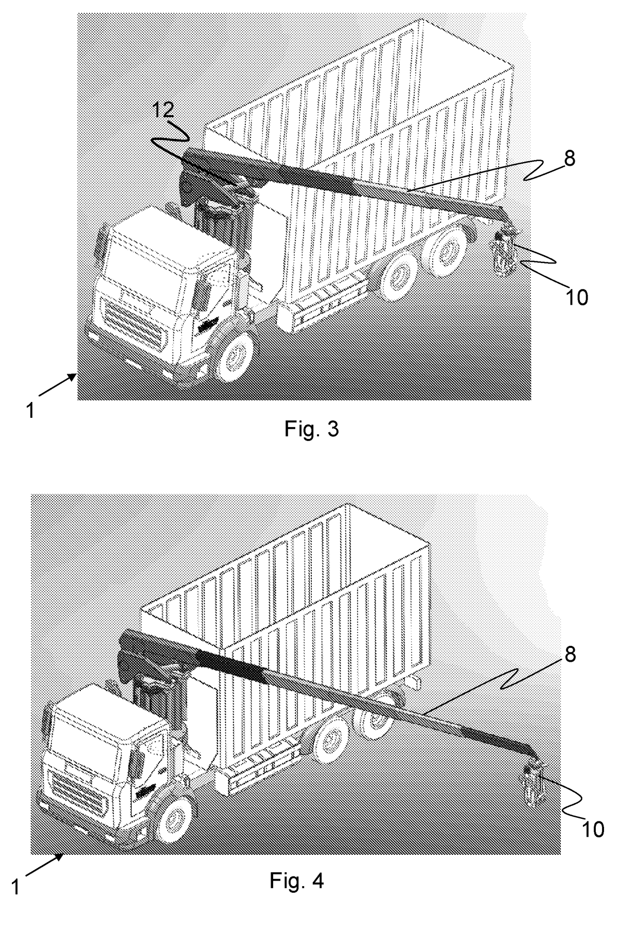
[0027]FIG. 3 shows the boom 8 in a first extended position and FIG. 4 shows it in a second, further extended position, wherein the boom 8 is approximately horizontal. The horizontal pivot angle is restricted in the collapsed state of the support 4 by the cargo space 3: on ...


PUM


Abstract

A lifting device on a heavy goods vehicle is described, for lifting and emptying waste collection containers, having a telescopically extensible boom, which has a coupling tool for coupling to a waste collection container. An extensible support is attached on a rotating platform and has at least one interleaved, telescopically extensible profile, wherein the boom is provided at the upper end of the support with a pivot element between boom and support, so that the boom is pivotable in a vertical plane about a pivot axis. The extensible profile is designed as an internal runner having a fixed tube and runners having a polygonal footprint, and a carrier head is provided at the end of the support, which is formed as L-shaped having an overhanging carrier plate in relation to the support, which carrier plate has the pivot axis of the boom and a support for the pivot element.

Description

BACKGROUND[0001]Technical Field[0002]The disclosure relates to a lifting device on a heavy goods vehicle for lifting and emptying waste collection containers.[0003]Description of the Related Art[0004]Such a lifting device for handling and emptying waste collection containers is known, for example, from WO-A-2012 / 032438. The lifting device described therein has a coupling tool for coupling to a waste collection container, and is provided with a rotating platform and a support attached thereon for a telescopically extensible boom. The support has interleaved C profiles, which are telescopically displaceable. The boom is fastened on the free end region of the support so it is vertically pivotable about a pivot axis. Furthermore, a pivot cylinder is provided between the boom and the support, to move the boom into a specific pivot angle in relation to the horizontal.[0005]The C profiles of this lifting device have oval openings to save weight, whereby the support of the above lifting dev...

Claims


Application Information

Patent Timeline
IPC IPC(8): B65F3/02B66C23/58B60P1/54B66C23/70B66C23/84B66C23/42B66C23/68
CPCB66C23/42B66C23/58B66C23/68B65F3/0203B66C23/84B60P1/5433B66C23/701B66C23/54B65F2003/0266B66C23/16
Inventor VILLIGER, PAUL
Owner VILLIGER PUBLIC SYST
Why Eureka
Try Eureka