Optical Imaging Lens and Lens Assembly

a technology of optical imaging and lens assembly, applied in the field of optical imaging, can solve the problems of difficult to reduce other factors that affect the image quality, coma, and various aberrations of the optical imaging system, and achieve the effects of reducing the manufacturing cost of the optical imaging lens, reducing the chromatic aberration, and high resolution quality

Active Publication Date: 2017-06-29
NINGBO SUNNY AUTOMOTIVE OPTECH
View PDF16 Cites 28 Cited by
  • Summary
  • Abstract
  • Description
  • Claims
  • Application Information

AI Technical Summary

Benefits of technology

[0009]The main object of the present invention is to provide a lens assembly for an optical imaging lens, wherein the optical imaging lens employing the lens assembly has a smaller optical length so that the optical imaging lens is easier to be miniaturized. In other words, the optical imaging lens employing the lens assembly can be more easily miniaturized while achieving higher image quality. Another advantage of the invention is to provide.
[0010]Another object of the present invention is to provide a lens assembly for the optical imaging lens, wherein the optical imaging lens employing the lens assembly can obtain higher resolution quality utilizing fewer lenses.
[0011]Another object of the present invention is to provide a lens assembly for the optical imaging lens, wherein the lens assembly preferably forms two cemented-type achromatic lenses so that the optical imaging lens employing the lens assembly has a smaller chromatic aberration.
[0012]Another object of the present invention is to provide a lens assembly for the optical imaging lens, wherein the aspheric mirror of the lens assembly can be made of plastic material to reduce the manufacturing cost of the optical imaging lens and to reduce the weight of the optical imaging lens.
[0013]Another object of the present invention is to provide a lens assembly for the optical imaging lens, wherein each of the lenses of the lens assembly can be made of glass material so that the optical imaging lens employing the lens assembly can clearly and stably image over a large range of temperature.
[0014]Another object of the present invention is to provide a lens assembly for the optical imaging lens, wherein the lens assembly can still achieve high image quality when using a large number of spherical lenses. In other words, under the premise of achieving high quality imaging, the lens assembly can still employ a plurality of glass spherical lenses, so that the optical imaging lens employing the lens assembly has better temperature stability so as to avoid the necessity of using aspherical glass lenses and the manufacturing cost of the optical imaging lens being increased.

Problems solved by technology

Optical imaging systems are subject to various aberrations, such as spherical aberration, coma, astigmatism, field curvature, and distortion.
However, when the imaging optical system only employs a single achromatic lens to achieve imaging, it is difficult to reduce other factors that affect the image quality, and a single achromatic lens to achieve good imaging need to use a ultra-low dispersion lens (ED lens), for example, a lens made of fluorite.
Fluorite is very difficult to process and high in cost, and its production process brings environmental pollution.
In addition, fluorite is fragile, which results in the entire optical imaging lens is not suitable for being used in complex and harsh environments.

Method used


Image

  • Optical Imaging Lens and Lens Assembly
  • Optical Imaging Lens and Lens Assembly
  • Optical Imaging Lens and Lens Assembly

Examples


Embodiment Construction

[0073]The following description is disclosed to enable any person skilled in the art to make and use the present invention. Preferred embodiments are provided in the following description only as examples and modifications will be apparent to those skilled in the art. The general principles defined in the following description would be applied to other embodiments, alternatives, modifications, equivalents, and applications without departing from the spirit and scope of the present invention.

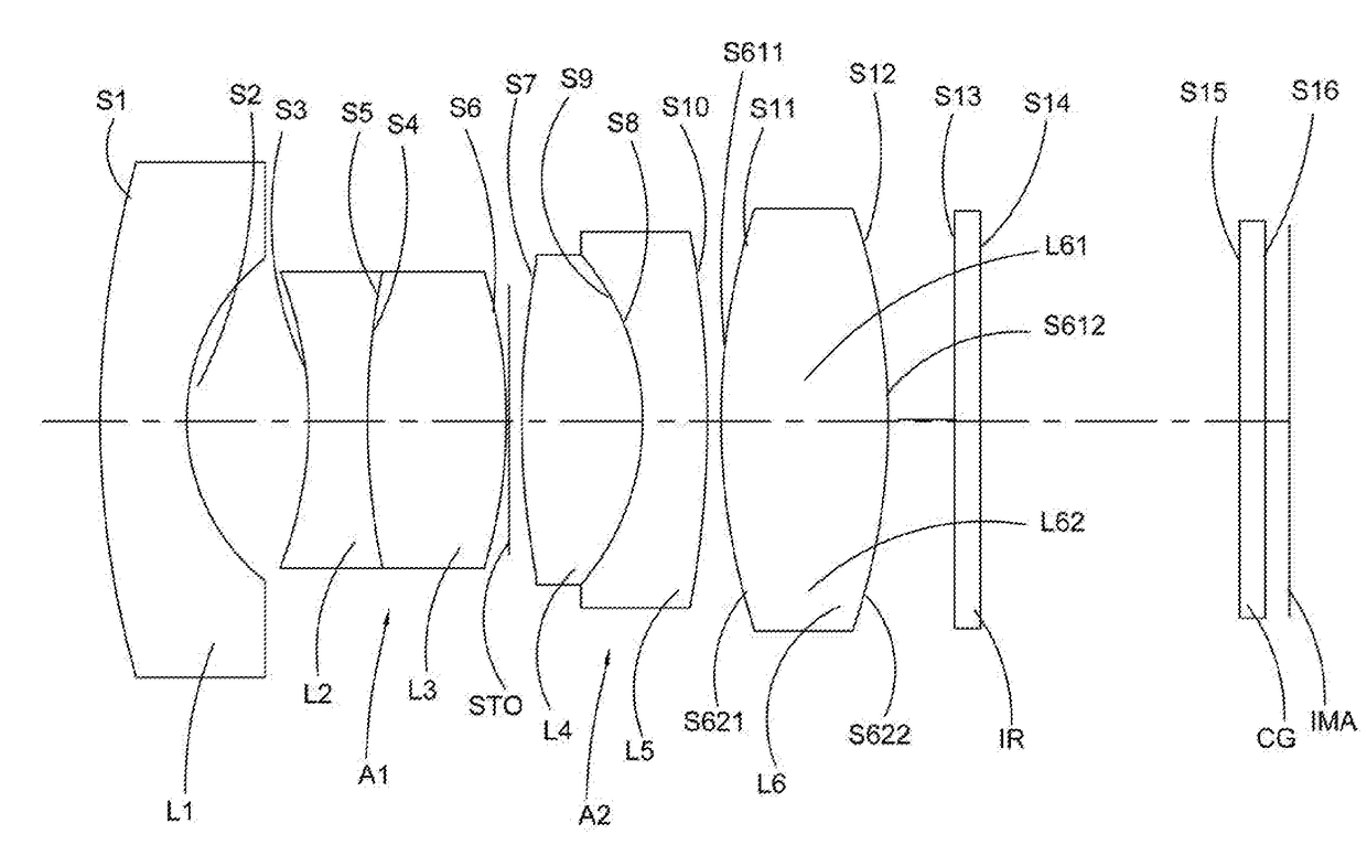
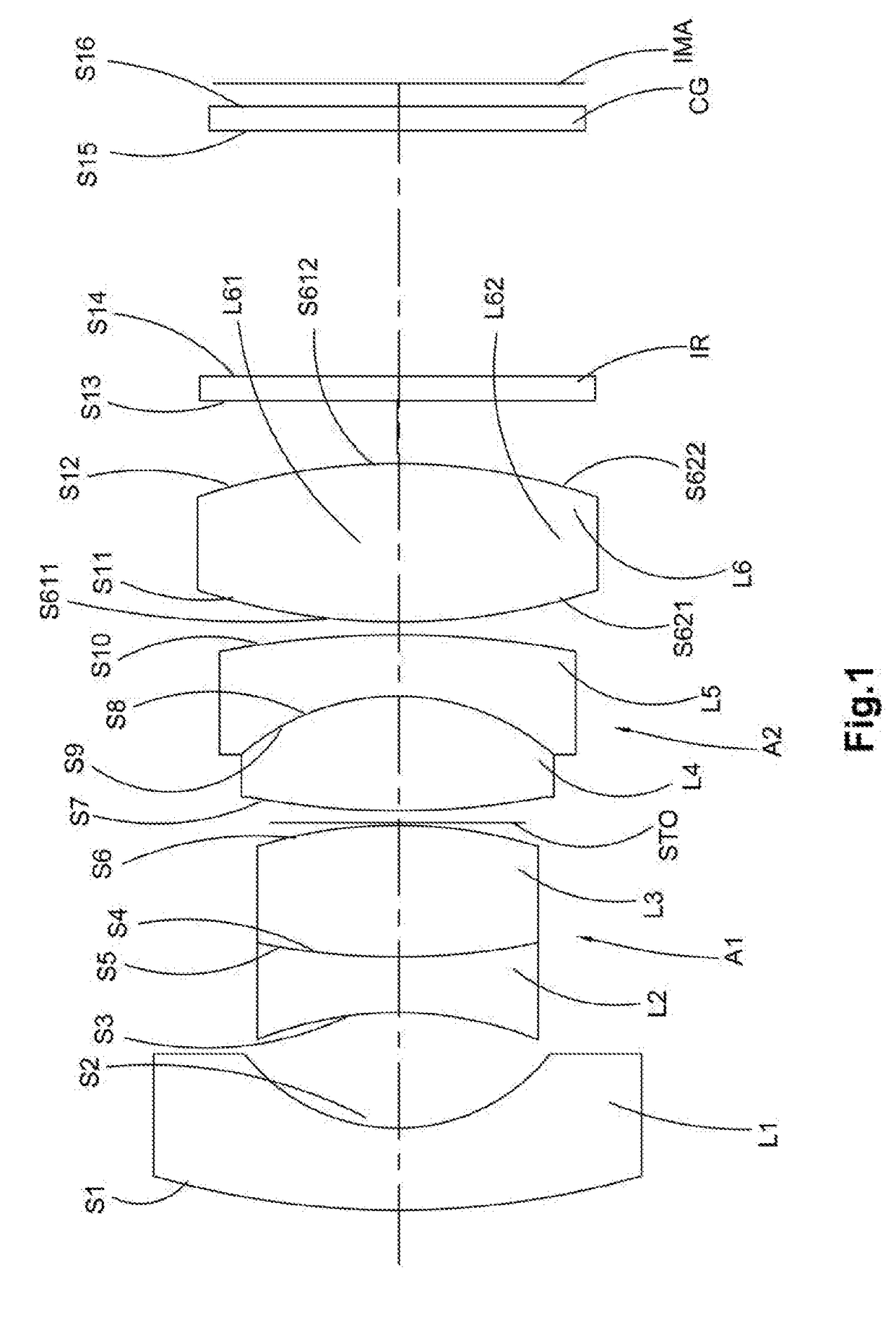
[0074]Referring to FIGS. 1 to 4 of the accompanying drawings of the present invention, a lens assembly for an optical imaging lens according to a first preferred embodiment of the present invention is illustrated, wherein the lens assembly of the optical imaging lens includes at least a first lens L1, a second lens L2, a third lens L3, a fourth lens L4, a fifth lens L5 and a sixth lens L6, wherein the first lens L1 has a negative power, and the sixth lens L6 has a positive power, wherein the seco...


PUM


Abstract

A lens assembly for an optical imaging lens is disclosed, which includes a first lens, wherein the first lens has a negative power, a second lens, a third lens, a fourth lens, a fifth lens, and a sixth lens, wherein the sixth lens has a positive power, wherein the second lens and the third lens define a first cemented achromatic lens assembly, and the fourth lens and the fifth lens define a second cemented achromatic lens assembly, wherein the first lens, the first cemented achromatic lens assembly, the second cemented achromatic lens assembly and the sixth lens are orderly arranged along the direction from the object side to the image side.

Description

CROSS REFERENCE OF RELATED APPLICATION[0001]This is an application that claims the benefit of priority under 35U.S.C. §119 to a non-provisional application, Chinese application number CN201511035710.9, filed 2016 Dec. 24.NOTICE OF COPYRIGHT[0002]A portion of the disclosure of this patent document contains material which is subject to copyright protection. The copyright owner has no objection to any reproduction by anyone of the patent disclosure, as it appears in the United States Patent and Trademark Office patent files or records, but otherwise reserves all copyright rights whatsoever.BACKGROUND OF THE PRESENT INVENTION[0003]Field of Invention[0004]The present invention relates to the field of optical imaging, and more particularly to an optical imaging lens. The invention further relates to a lens assembly for an optical imaging lens.[0005]Description of Related Arts[0006]Optical imaging systems, and in particular refracted optical imaging systems, often require optical imaging l...

Claims


Application Information

Patent Timeline
Patent Type & Authority Applications(United States)
IPC IPC(8): G02B13/00G02B27/00G02B5/00G02B9/62G02B5/20
CPCG02B13/006G02B9/62G02B27/0025G02B5/20G02B5/005G02B13/0045G02B13/18
Inventor WANG, DONGFANGYAO, BOXIE, QIANSEN
Owner NINGBO SUNNY AUTOMOTIVE OPTECH
Why Eureka
Try Eureka