
Method and apparatus for automatically generating a component fault tree of a safety-critical system

a technology of safety-critical systems and fault trees, which is applied in the direction of fault response, reliability/availability analysis, instruments, etc., can solve the problems of cumbersome and prone to errors of complex safety-critical systems

Active Publication Date: 2017-06-29
SIEMENS AG
View PDF4 Cites 15 Cited by
  • Summary
  • Abstract
  • Description
  • Claims
  • Application Information

AI Technical Summary

Benefits of technology

The present patent provides a method and apparatus for automatically generating a component fault tree of a safety-critical system. This helps to improve the efficiency and accuracy of fault tree analysis and root cause analysis in safety-critical systems. The method involves receiving a continuous function chart for each system component and generating a corresponding component fault tree element based on the functions of the chart. The fault tree elements are then interconnected based on the unique names of the inputs and outputs of the chart. The method also includes generating input and output failure modes for each fault tree element and connecting them via internal failure propagation paths. The apparatus includes an input for receiving a continuous function chart, a processing unit for generating the component fault tree elements, and an output for outputting the generated fault tree. The technical effects of this patent include improved efficiency and accuracy in fault tree analysis and root cause analysis, as well as improved safety-critical system design and development.

Problems solved by technology

However, the generation of a component fault tree of a complex safety-critical system may be cumbersome and prone to errors since it is mostly done manually by a safety engineer.

Method used


Image

  • Method and apparatus for automatically generating a component fault tree of a safety-critical system
  • Method and apparatus for automatically generating a component fault tree of a safety-critical system
  • Method and apparatus for automatically generating a component fault tree of a safety-critical system

Examples


Embodiment Construction

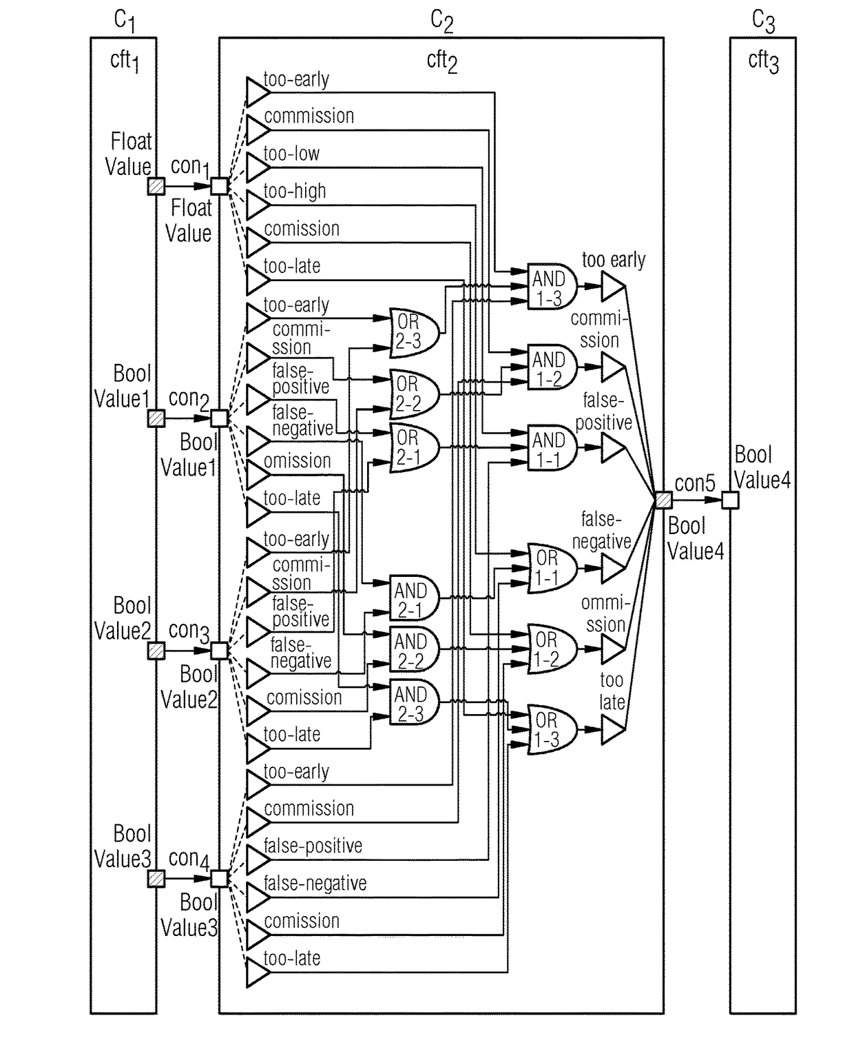
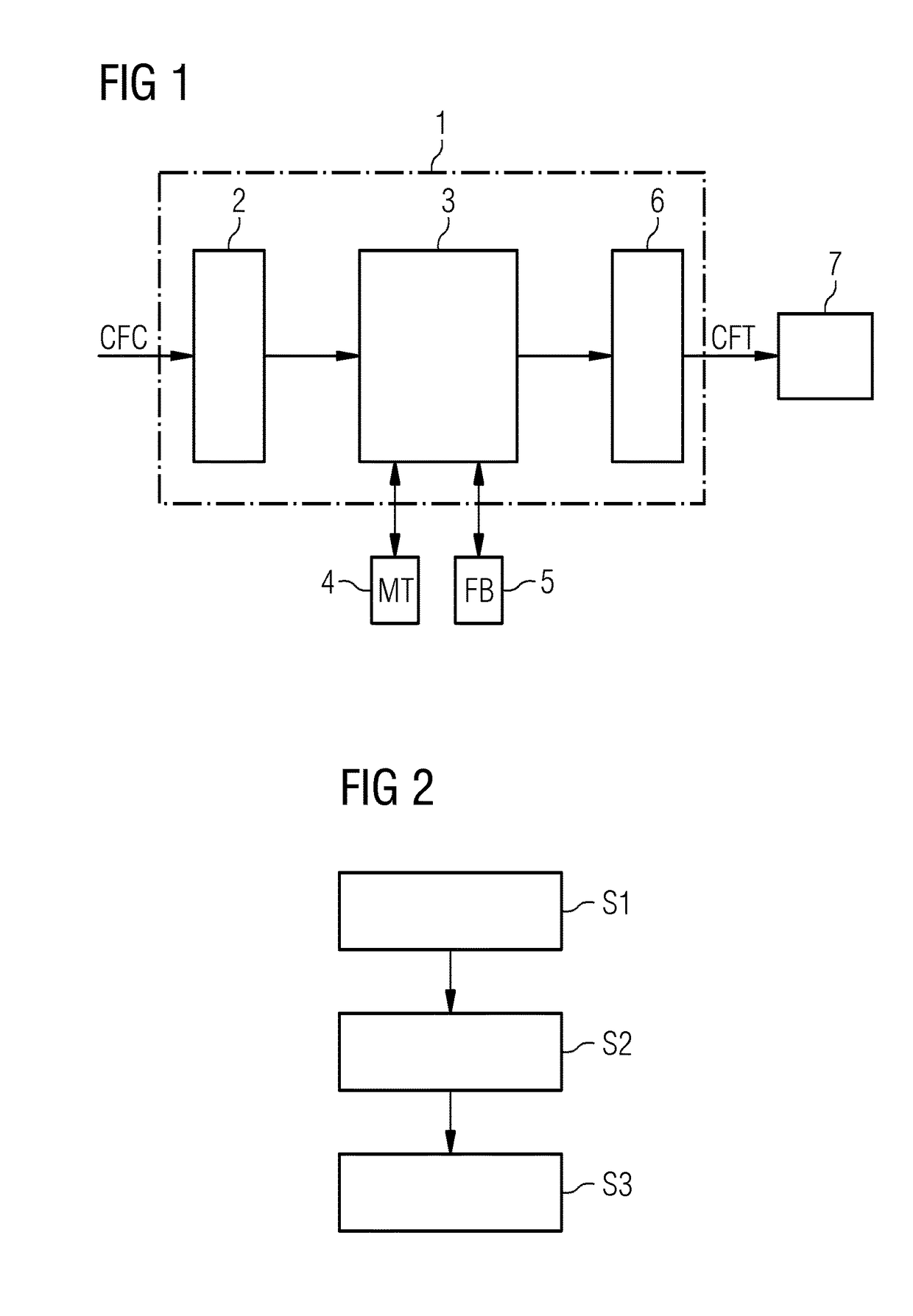
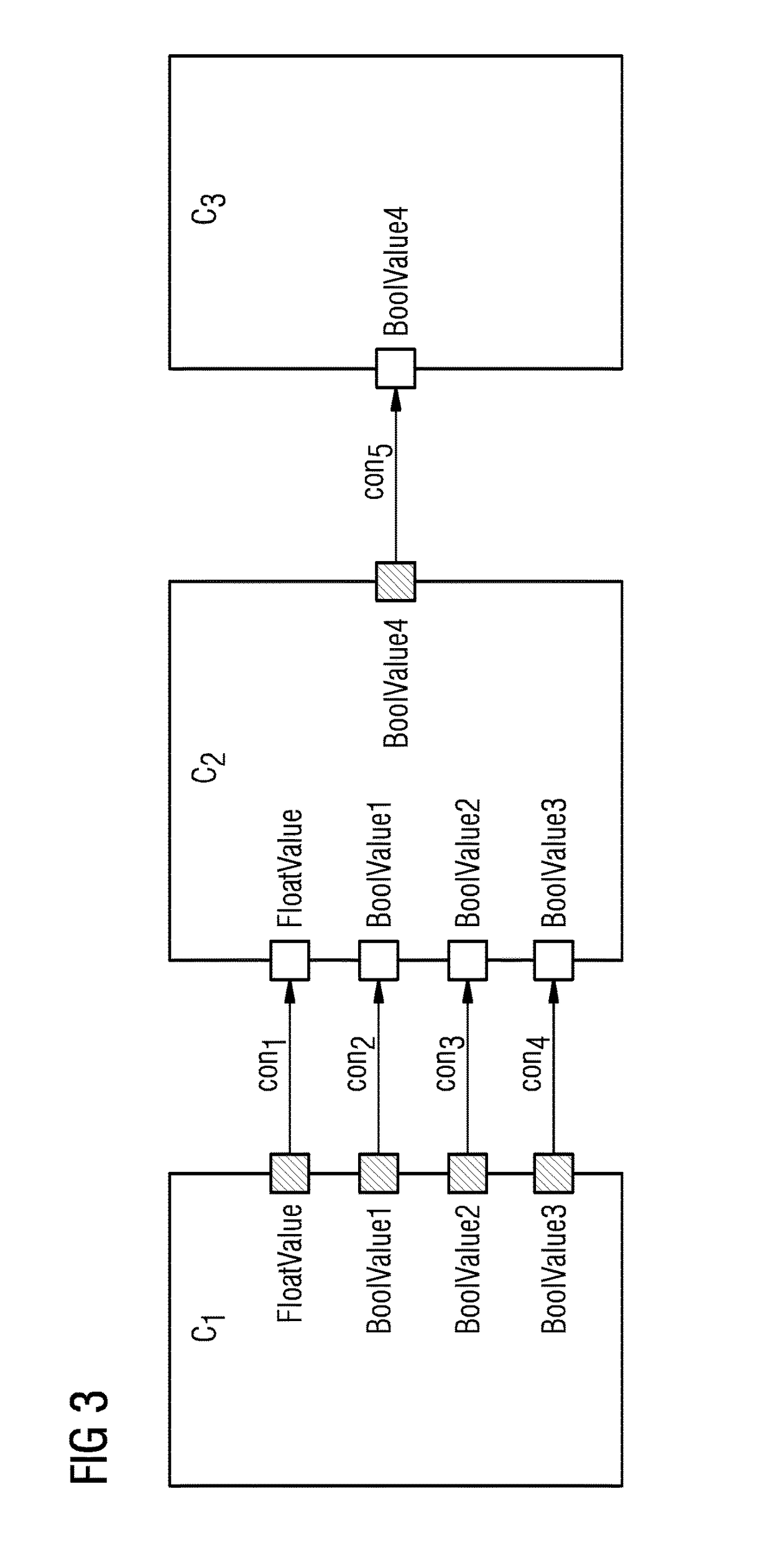
[0028]FIG. 1 shows an exemplary embodiment of an apparatus 1 for generating automatically a component fault tree of an investigated safety-critical system SYS according to an aspect. The apparatus 1 is adapted to generate automatically a component fault tree CFT of an investigated safety-critical system SYS. The safety-critical system SYS may include a complex safety-critical system including a plurality of software components and / or hardware components. The apparatus 1 includes an input 2 formed by an interface to receive a continuous function chart CFC for each system component C of the investigated safety-critical system SYS.

[0029]The apparatus 1 further includes a processing unit 3 adapted to generate for each continuous function chart CFC a corresponding component fault tree, CFT, element. Inports and outports of the component fault tree, CFT, elements are generated and interconnected by the processing unit 3 of the apparatus 1 based on unique names of the inputs and outputs of...


PUM


Abstract

An apparatus includes an input that receives a continuous function chart for each component of the investigated safety-critical system. A processor generates a corresponding component fault tree element. Inports and outports of the component fault tree element are generated and interconnected based on unique names of the inputs and outputs of the corresponding continuous function chart of the respective system component. Input failure modes and output failure modes are generated based on generic mapping between connector types of the continuous function chart and failure types of failure modes of the component fault tree element. The input failure modes of a component fault tree element are connected to output failure modes of the component fault tree element via internal failure propagation paths based on interconnected function blocks of the continuous function chart of the respective system component. An output outputs the generated component fault tree of the safety-critical system.

Description

TECHNICAL FIELD[0001]The present embodiments relate to a method and apparatus for generating automatically a component fault tree of a safety-critical system on the basis of continuous function charts of system components of the respective safety-critical system.TECHNICAL BACKGROUND[0002]Safety-critical systems may be found in a wide range of technical domains such as aerospace, transport systems, healthcare systems, automotive systems and industrial automation systems. With the growing system complexity of such safety-critical systems, also the need for safety assessment of the safety-critical system is increasing in order to meet the high quality demands in these technical domains. The goal of a safety assessment process is to identify all failures that cause hazardous situations and to demonstrate that the probability of occurrence of such failures is sufficiently low. In the application domains of safety-critical systems, the corresponding safety assurance process may be defined...

Claims


Application Information

Patent Timeline
Patent Type & Authority Applications(United States)
IPC IPC(8): G06F11/07G06F17/30
CPCG06F11/0769G06F17/30312G06F11/0721G06F11/008G06F16/22G06F11/2252G06F11/2257G06F11/0736G06F11/079
Inventor HOFIG, KAIZELLER, MARC
Owner SIEMENS AG
Learn More