
Device for the acquisition and conditioning of an acoustic signal generated by a source of an internal combustion engine

Active Publication Date: 2017-06-29
MARELLI EURO SPA
View PDF5 Cites 0 Cited by
  • Summary
  • Abstract
  • Description
  • Claims
  • Application Information

AI Technical Summary

Benefits of technology

The present invention aims to provide a device that can collect and condition the acoustic signals generated by a source in the engine compartment of a vehicle. The device overcomes the shortcomings of existing devices and is easy and inexpensive to produce.

Problems solved by technology

In particular, the application of the sensor directly onto the control unit of the internal combustion engine is limiting from the positioning flexibility point of view, because of the constraints imposed by the size of the electronic control unit.
In addition, these solutions have considerable costs, which are related to the signal processing electronic components, which are provided on the measuring device itself.

Method used


Image

  • Device for the acquisition and conditioning of an acoustic signal generated by a source of an internal combustion engine
  • Device for the acquisition and conditioning of an acoustic signal generated by a source of an internal combustion engine
  • Device for the acquisition and conditioning of an acoustic signal generated by a source of an internal combustion engine

Examples


first embodiment

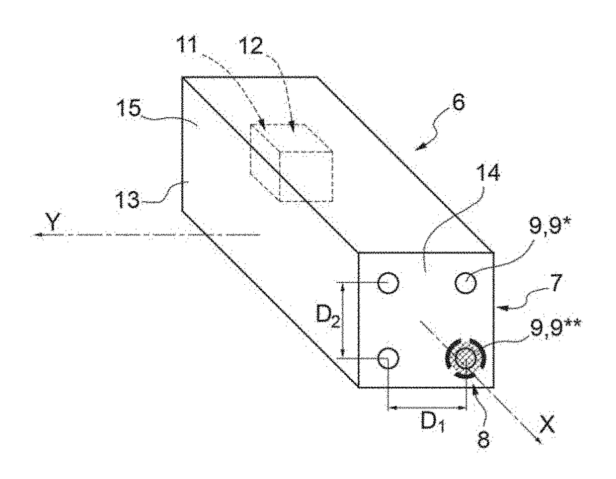
[0023] shown in FIG. 2, the support body 13 has the measuring assembly 7 in the area of a front wall 14 and the measuring assembly 8 in the area of a side wall 15, arranged orthogonal to the front wall 14. In other words, the measuring assembly 7 is formed in the area of the front wall 14 that is arranged orthogonal to the provenance direction X; whereas the measuring assembly 8 is formed in the area of the side wall 15 that is arranged orthogonal to the provenance direction Y. In this case, the provenance direction X is orthogonal to the provenance direction Y.

[0024]In this embodiment, the measuring assembly 7 comprises, respectively, at least two microphones 9*, in particular four microphones 9* arranged in two rows and two columns and equally spaced from one another. Similarly, the measuring assembly 8 comprises, respectively, at least one microphone 9**, in particular four microphones 9** arranged in two rows and two columns and equally spaced from one another.

second embodiment

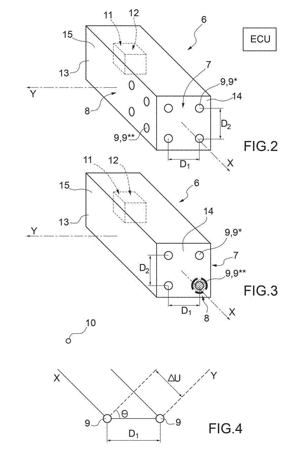
[0025] shown in FIG. 3, the support body 13 has both the measuring assembly 7 and the measuring assembly 8 in the area of the front wall 14.

[0026]In this embodiment, the measuring assembly 7 comprises three microphones 9*, while the measuring assembly 8 is formed with a single microphone 9**. The four microphones 9 are arranged in two rows and two columns and are equally spaced from one another. The measuring assembly 8 is obtained by screening a microphone 9. In this way, despite being arranged with the same orientation of the microphones 9*, the microphone 9** will not be able to detect the signal SX in the provenance direction X (being screened along said provenance direction X) and can only acquire the signal SY along the provenance direction Y.

[0027]In other words, in this embodiment, the detection assemblies 7, 8 are arranged in the area of the same front wall 14 of the support body 13 which is arranged orthogonal to the provenance direction X, but at least one of the micropho...

third embodiment

[0040] not shown, the device is provided with a further measuring assembly equipped with at least one microphone 9**. In particular, the measuring assembly 16 is adapted to acquire the sound signal S along a third direction, different with respect to the directions X and Y, so as to obtain a spatial directivity.

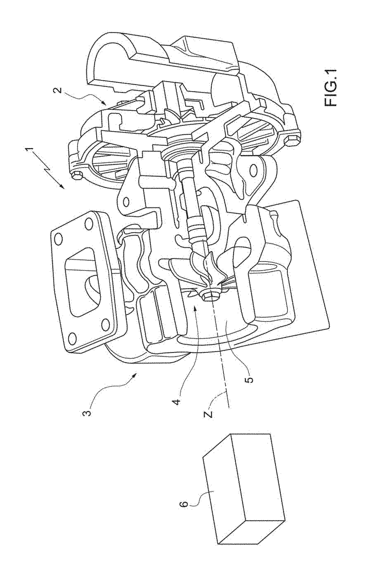
[0041]In the foregoing description, reference was explicitly made to the processing of the sound signal S generated by rotation of the bladed disk 4 of the turbocharger 1*, but the device 6 for the acquisition and conditioning can be used for the processing of the sound signal S generated by any component arranged in the engine compartment.

[0042]It is to be understood that, depending on the phenomena to be measured or monitored, it is possible to arrange special filtering chains that allow for isolating the components at different frequencies typical of related phenomena.

[0043]The device 6 for the acquisition and conditioning of the sound signal S described hitherto has a few...


PUM


Abstract

A device for the acquisition and conditioning of a sound signal generated by a source of an internal combustion engine and comprising a box-shaped support body having a first measuring assembly and a second measuring assembly; wherein the first measuring assembly is provided with at least two first microphones which lie on a first plane and are configured for the detection of a first acoustic signal generated by the source along a first provenance direction; and wherein the second measuring assembly is provided with at least a second microphone arranged on a second plane configured for the detection of a second acoustic signal generated by the source along a second provenance direction different from the first provenance direction.

Description

[0001]The present invention relates to a device for the acquisition and conditioning of an acoustic signal generated by a source arranged in the engine compartment of a vehicle.BACKGROUND OF THE INVENTION[0002]In the automotive field, the use of sensors such as microphones and / or accelerometers is known for the acquisition of signals generated by a source inside the engine compartment which are then suitably processed by specific algorithms to obtain information concerning the components arranged in the engine compartment, such as for example the rotational speed of the turbocharger, the occurrence of knocking phenomena, ignition failure phenomena, the engine load, the closing of the intake and / or exhaust valves, etc.[0003]Typically, the sensors are installed directly onto the electronic control unit of the internal combustion engine or are housed on a measuring device provided with a processing unit (a microcontroller) for the signal, which is in turn connected to the electronic co...

Claims


Application Information

Patent Timeline
IPC IPC(8): H04R3/00G01M15/12
CPCH04R3/005H04R2430/20G01M15/12F02D41/1497G01H17/00F02D41/0007F02D2041/288F02D2200/025G01H3/125H04R2499/13Y02T10/12
Inventor DE CESARE, MATTEOCOVASSIN, FEDERICOBARBUTO, ANTONIOMONTI, FEDERICO
Owner MARELLI EURO SPA
Features
  • Generate Ideas
  • Intellectual Property
  • Life Sciences
  • Materials
  • Tech Scout
  • Unparalleled Data Quality
  • Higher Quality Content
  • 60% Fewer Hallucinations
Learn More