Schedule Aggregation and Antenna-Radiation-Pattern Optimization

a technology of antenna radiation pattern and schedule aggregation, applied in the field of schedule aggregation and antenna radiation pattern optimization, can solve problems such as difficulty in determining optimal antenna radiation pattern, and achieve the effect of reducing interferen

Active Publication Date: 2017-06-29
ARRIS ENTERPRISES LLC
View PDF6 Cites 21 Cited by
  • Summary
  • Abstract
  • Description
  • Claims
  • Application Information

AI Technical Summary

Benefits of technology

[0013]Moreover, during operation the interface circuit may: communicate with one or more portable electronic devices; and repeat transmitting the outgoing messages, receiving the transmit feedback, receiving the incoming messages, determining the re...

Problems solved by technology

However, it can be difficult to determine the optimal antenna radiation patterns (and, thus, the antenna-radiation-pattern settings) for the multiple antennas in transmitting devices and/or receiving devices.
In particular, determining the optimal antenna ra...

Method used


Image

  • Schedule Aggregation and Antenna-Radiation-Pattern Optimization
  • Schedule Aggregation and Antenna-Radiation-Pattern Optimization
  • Schedule Aggregation and Antenna-Radiation-Pattern Optimization

Examples


Embodiment Construction

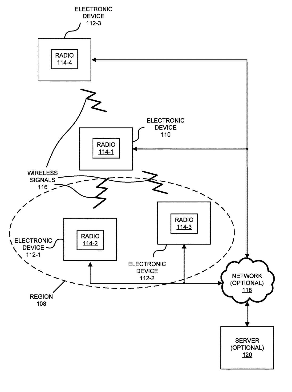
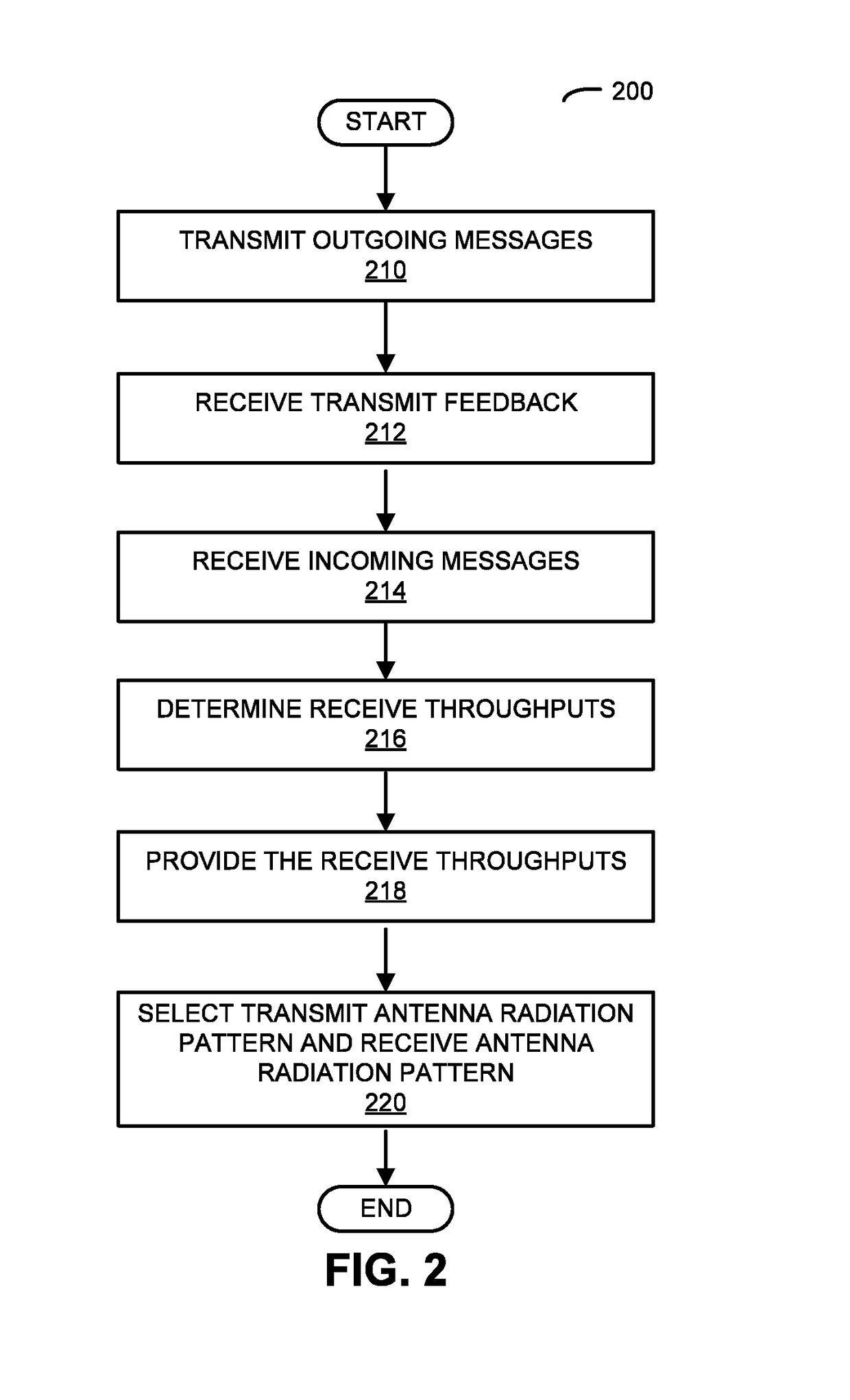
[0039]In one group of embodiments, an electronic device iteratively determines an optimal transmit antenna radiation pattern and an optimal receive antenna radiation pattern based on a feedback process with a second electronic device. First, the electronic device transmits outgoing messages to the second electronic device using a set of transmit antenna radiation patterns having different transmit spatial orientations. Based on throughput feedback from the second electronic device, the electronic device selects the optimal transmit antenna radiation pattern. Then, based on throughputs for incoming messages from the second electronic device that were received using a set of receive antenna radiation patterns having different receive spatial orientations, the electronic device selects the optimal receive antenna radiation pattern. Note that the transmit antenna radiation pattern and the receive antenna radiation pattern may reduce or eliminate interference between the electronic devic...


PUM


Abstract

An electronic device modifies a schedule of communication frequencies (such as an orthogonal frequency division multiplexing access schedule) by changing the times when subcarriers are used for communication with a set of electronic devices in order to cluster subsets of the set of electronic devices. This clustering may leave the throughput associated with the communication at least approximately unchanged. Then, the electronic device selects, for the subsets, transmit antenna radiation patterns and receive antenna radiation patterns in order to increase the throughputs during transmission and/or receiving.

Description

BACKGROUND[0001]Field[0002]The described embodiments relate to techniques for communicating information among electronic devices. In particular, the described embodiments relate to techniques for changing the coverage area during wireless communication in a cellular-telephone network by adapting transmit and / or receive antenna radiation patterns for the electronic devices.[0003]Related Art[0004]Many electronic devices are capable of wirelessly communicating with other electronic devices. For example, electronic devices often include a networking subsystem that implements a network interface for: a cellular network (UMTS, LTE, etc.), a wireless local area network (e.g., a wireless network such as described in the Institute of Electrical and Electronics Engineers (IEEE) 802.11 standard or Bluetooth™ from the Bluetooth Special Interest Group of Kirkland, Wash.), and / or another type of wireless network.[0005]In order to improve performance during wireless communication among electronic ...

Claims


Application Information

Patent Timeline
IPC IPC(8): H04W72/12H04B7/04H04L5/00
CPCH04W72/12H04B7/04H04L5/001H04B17/102H04B17/318H04B7/0617H04W72/541H04B7/0691H04L5/0023H04W16/28
Inventor SHTROM, VICTORPATEL, SANDIP C.MARTIN, STEVE A.
Owner ARRIS ENTERPRISES LLC
Why Eureka
Try Eureka