
Electronic apparatus

Active Publication Date: 2017-06-29
DELTA ELECTRONICS SHANGHAI CO LTD
View PDF2 Cites 10 Cited by
  • Summary
  • Abstract
  • Description
  • Claims
  • Application Information

AI Technical Summary

Benefits of technology

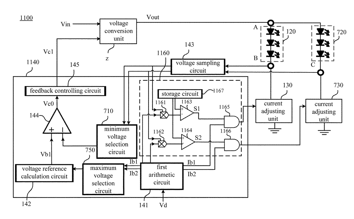
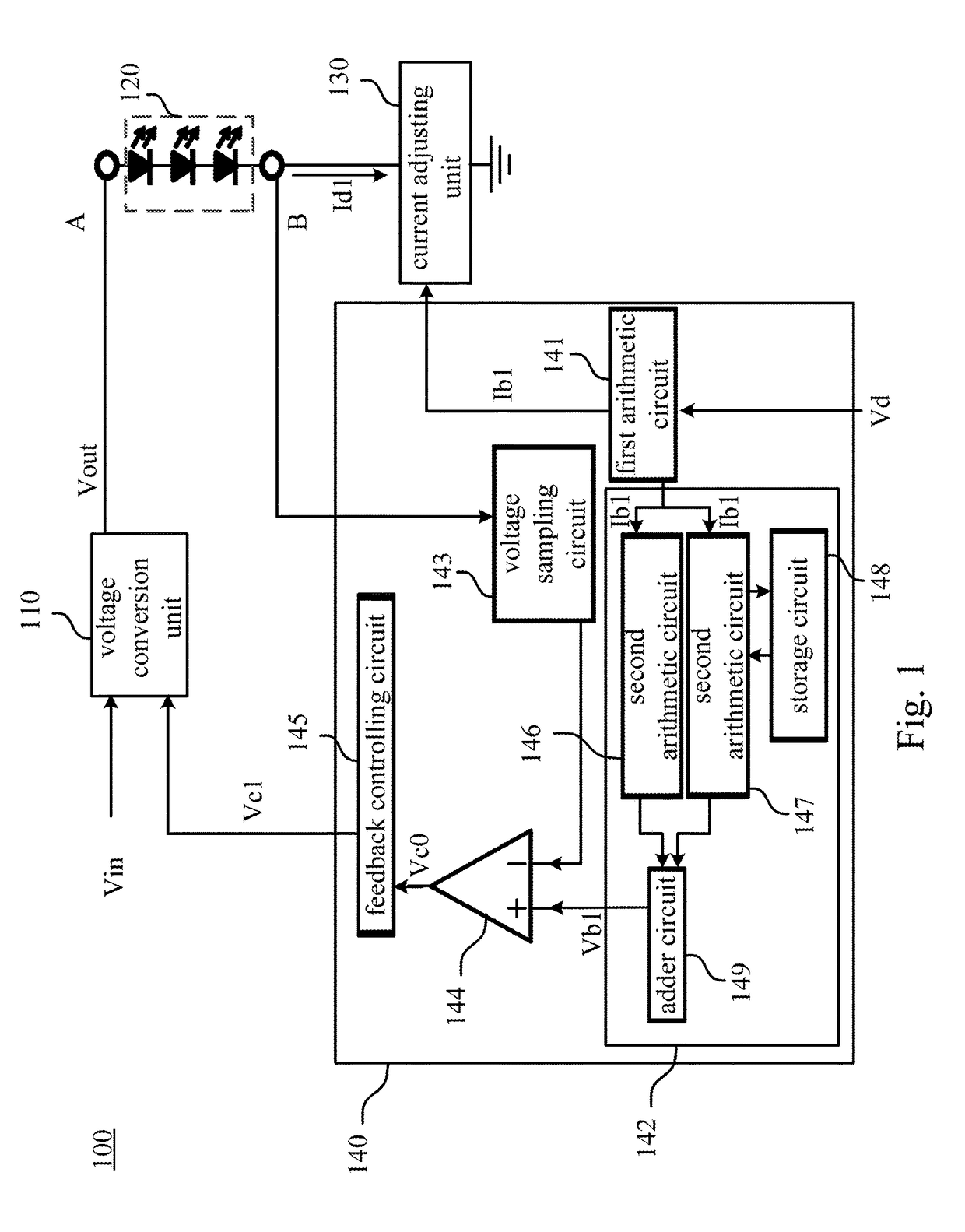
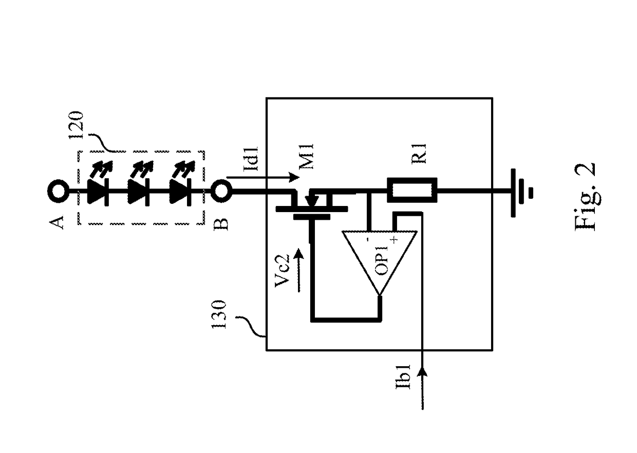
This patent invention aims to save power consumption in electronic devices by controlling the current reference signal and voltage conversion unit according to a control signal generated by a voltage reference signal. Additionally, it allows for individual protection of each path load in a multi-path load and expands the dimming range in a dimming application.

Problems solved by technology

However, as the maturity of the lighting technology or the semiconductor technology progresses, modern light emitting diode (LED) not only has high luminous efficiency but also saves on power consumption.
Due to the reference voltage for controlling the linear constant current circuit being a fixed value, the driver efficiency cannot be optimized under a light load condition.
However, in the application of multi-path load in parallel, the method cannot independently protect each path load of the multi-path load.
Therefore, the output voltages of the other path loads are affected when one path load of the multi-path load is short-circuited.
Further, the character of components in the general linear constant current circuit limits the driver.
Thus, the LED driver cannot achieve a wider dimming range.

Method used


Image

  • Electronic apparatus
  • Electronic apparatus
  • Electronic apparatus

Examples


Embodiment Construction

[0026]The following disclosure provides many different embodiments, or examples, for implementing different features of the provided subject matter. Specific examples of components and arrangements are described below to simplify the present disclosure. These are, of course, merely examples and are not intended to be limiting. For example, the formation of a first feature over or on a second feature in the description that follows may include embodiments in which the first and second features are formed in direct contact, and may also include embodiments in which additional features may be formed between the first and second features, such that the first and second features may not be in direct contact. In addition, the present disclosure may repeat reference numerals and / or letters in the various examples. This repetition is for the purpose of simplicity and clarity and does not in itself dictate a relationship between the various embodiments and / or configurations discussed.

[0027]T...


PUM


Abstract

An electronic device comprises a voltage conversion unit, a first load unit, a current adjusting unit, and a control unit. The voltage conversion unit is configured to transfer an input voltage to an output voltage. The current adjusting unit electrically is coupled with the second terminal of the load unit. The current adjusting unit is configured to control a first driving current flowing through the first load unit according to a first current reference signal. The control unit is electrically coupled with the first load unit and the voltage conversion unit. The control unit is configured to generate a first voltage reference signal according to the first current reference signal and generate a first control signal to the voltage conversion unit according to a voltage of the second terminal of the first load unit and the first voltage reference signal.

Description

RELATED APPLICATIONS[0001]This application claims priority to China Application Serial Number 201511005943.4, filed Dec. 28, 2015, which is herein incorporated by reference.BACKGROUND[0002]Field of Invention[0003]The present invention relates to an electronic device. More particularly, the present invention relates to an electronic device for saving power consumption.[0004]Description of Related Art[0005]Most modern lighting devices have adopted incandescent bulbs or fluorescent tubes. However, as the maturity of the lighting technology or the semiconductor technology progresses, modern light emitting diode (LED) not only has high luminous efficiency but also saves on power consumption. Therefore, there is a significant demand for LEDs, which are now flourishing.[0006]However, the current common LED driver usually consists of a direct current (DC) voltage source and a linear constant current circuit. In order to reduce loss of the linear constant current circuit, the output voltage ...

Claims


Application Information

Patent Timeline
IPC IPC(8): H05B33/08H05B44/00
CPCH05B33/0851H05B33/0884G05F1/56H05B45/50H05B45/395H05B45/46Y02B20/30H05B45/56H05B45/10
Inventor CHEN, JIANFU, XIAO-PINGZHANG, XING-HUA
Owner DELTA ELECTRONICS SHANGHAI CO LTD
Learn More