Dip fusion spike screw

a technology of fusion spike screw and dip screw, which is applied in the direction of internal osteosynthesis, internal osteosynthesis, osteosynthesis devices, etc., can solve the problems of pain, loss of mobility, damage to the articular surface, etc., and achieve the effect of convenient placemen

Active Publication Date: 2017-07-06
EXSOMED CORP
View PDF5 Cites 17 Cited by
  • Summary
  • Abstract
  • Description
  • Claims
  • Application Information

AI Technical Summary

Benefits of technology

The device described in this patent text can be tapered to a tip or cannulated. It is designed to be easy to place and resistant to bending or breaking during use. The middle portion of the device is thicker than the second end, which helps to strengthen it.

Problems solved by technology

Damage to the joints may occur as a result of arthritis, a sprain or fracture, and wherein the damage either directly or indirectly affects the articular cartilage.
Typically, the joint does not line up the same after the injury and causes unusual wear on the articular cartilage, eventually damaging the articular surface and causing pain and loss of mobility.
Existing methods of fusion are inadequate, such as (a) K-wire fusion, (b) or inserting a screw through the tip of the finger and through the joint to be fused because the joint is typically fused straight (i.e., without a bend in it), which is not a natural position for the joint of a finger during normal use.
Herbert and Acutrack screws and their variants have been used, but by using these, the joint (DIP joint) and end of the finger are fused in a straight position, which is unnatural since the joint is normally bent during use.
DIP fusions with angles can be performed but the process is technically demanding, so it is rarely performed.
Additionally, the ability to angle the joint is limited and the bone purchase is poor.
Other techniques such as pin and tension band or cerclage wire do not adequately solve the problem of easily fusing a finger joint in a bent position.

Method used


Image

  • Dip fusion spike screw
  • Dip fusion spike screw
  • Dip fusion spike screw

Examples


Embodiment Construction

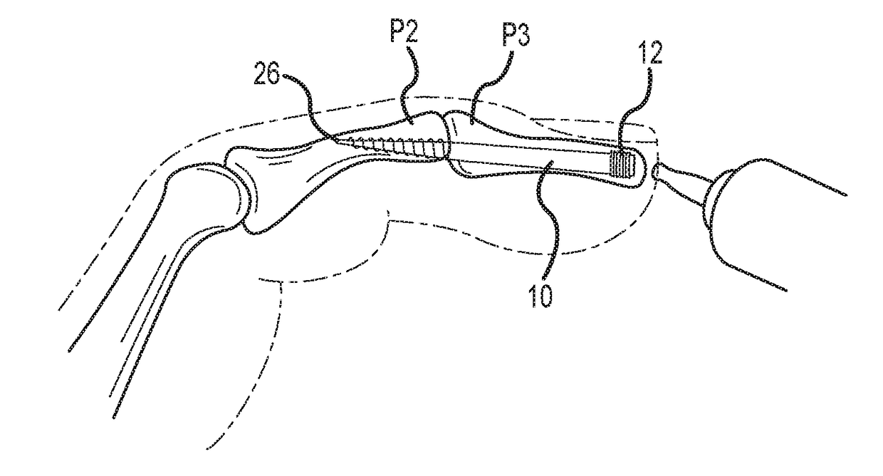
[0025]A device or method according to the invention allows for the fusion of joints in the finger (particularly the DIP joint) in a bent (or angled) position, which is more natural when using the hand. For a finger joint, fusing the joint in a bent position allows for the patient to be able to better grip things after a successful procedure and fusion of a joint. In certain embodiments, a device for the fusion of small finger joints preferably allows for one or more of various angled positions, and the particular angle may differ for different joints. The device is preferably a screw for fusing together bones or a joint, and most preferably is used for fusing bones or a joint in a finger or toe.

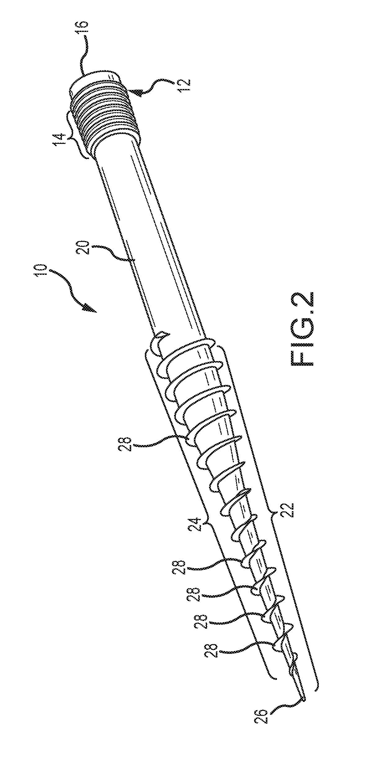
[0026]With reference to FIG. 2, in one embodiment, the device is a screw 10 that has a first end 12 having a first threaded portion 14, and a driver head 16. It also has a central portion 20, which is substantially cylindrical and preferably of a single diameter. It preferably has a second 22...


PUM


Abstract

Devices and methods are disclosed for the fusion of joints (particularly finger joints or toe joints) in a bent (or angled) position. The device is not cannulated, straight and inserted into the joint in its straight configuration. The device is configured to have a thicker portion at its proximal end than at its distal end. The device is preferably inserted into a finger joint that is already bent at an angle, and the thin, distal end is configured to screw into and attach to the bone of second joint thereby fusing the first joint to the second joint.

Description

FIELD OF THE INVENTION[0001]The present invention relates to a device or method for the fusion of a joint, particularly the DIP joint of a finger, in a predetermined position.BACKGROUND OF THE INVENTION[0002]The palm of the hand is made up of bones called metacarpals, and a metacarpal connects each finger and thumb to the hand. Each finger and thumb is formed of bones called phalanges. The connection of the phalanges to the metacarpals is called a “knuckle” joint or metacarpophalangeal joint (MCP joint), and acts like a hinge when the fingers or thumb are bent.[0003]In each finger, there are three phalanges that are separated by two joints called the interphalangeal joints (IP joints). The proximal IP joint (PIP joint) is the one closest to the MCP joint. The other joint closest to the end of the finger is the distal IP joint (DIP joint). The thumb just has one IP joint.[0004]The joints are covered on the ends with articular cartilage. Damage to the joints may occur as a result of a...

Claims


Application Information

Patent Timeline
IPC IPC(8): A61B17/86
CPCA61B17/863A61B17/86A61B17/8635A61B17/7291
Inventor CHAMPAGNE, LLOYD P.ZOLDOS, JOZEF
Owner EXSOMED CORP
Why Eureka
Try Eureka