Injection nozzle with finish cooling and counter pressure

Active Publication Date: 2017-07-06
DISCMA
View PDF3 Cites 3 Cited by
  • Summary
  • Abstract
  • Description
  • Claims
  • Application Information

AI Technical Summary

Benefits of technology

[0009]In satisfying the above need, as well as overcoming the enumerated drawbacks and other limitations of the prior art, in one aspect of the present invention, an injection nozzle for receiving a neck of a preform and forming of a container from the preform is provided. The injection nozzle includes a nozzle body provided at one end of the injection nozzle, and the nozzle body defining a receiving space adapted to receive the finish of the preform, at least one inlet passageway defined through the nozzle body and communicating with the receiving space, characterized by the fact that the nozzle body is a manifold defining a cavity and portions of the cavity being defined by an inner wall and an outer wall of the manifold, a plurality of ports defined through the inner wall and communicating the cavity with the receiving space, the at

Problems solved by technology

In view of the above, it is apparent that there exists a need for a system in which the finish of a preform is protected during the hydraulic blow molding process, not only from p

Method used


Image

  • Injection nozzle with finish cooling and counter pressure
  • Injection nozzle with finish cooling and counter pressure
  • Injection nozzle with finish cooling and counter pressure

Examples


Example

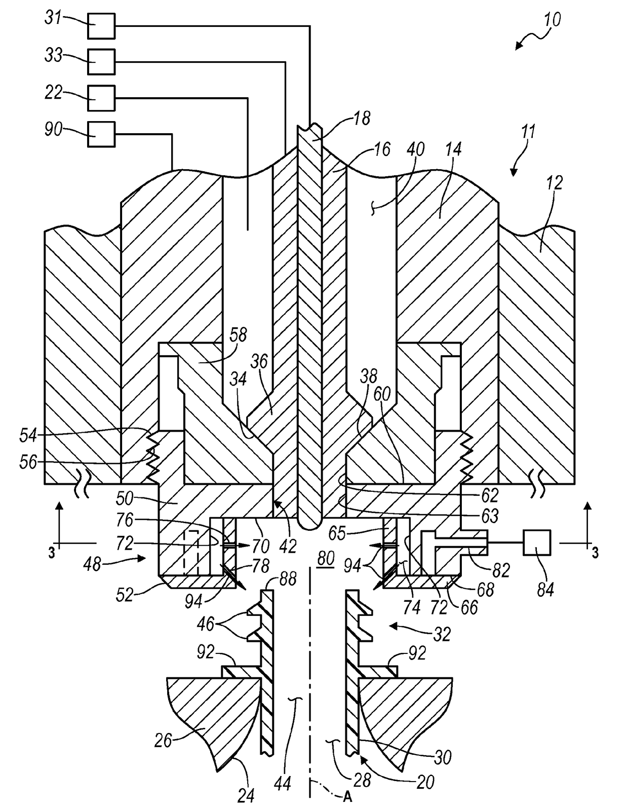
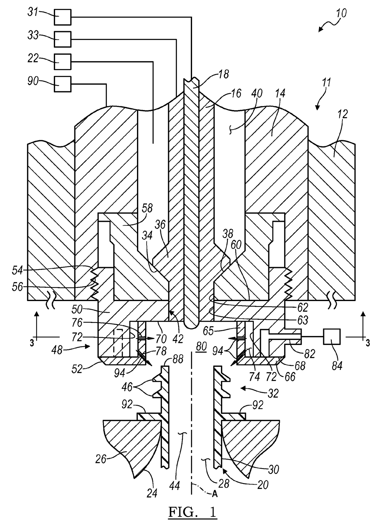
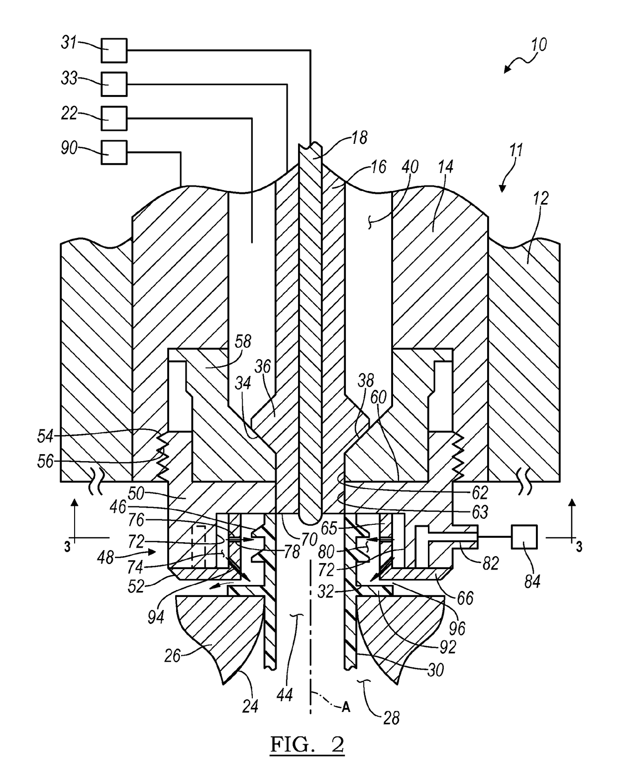
[0047]Referring now to the drawings, a hydraulic blow molding machine, used to form a container from a preform, and embodying the principles of the present invention, is schematically illustrate in the figures and generally designated at 10. As its primary components, and as seen in FIGS. 1 and 2, the hydraulic blow molding machine 10 includes an injection head 11 having a housing 12 within which are coaxially located an injection nozzle 14, a seal pin 16 and a stretch rod 18.

[0048]The injection head 11 is coupled to a source of blow medium 22 (a liquid that is also the end product retained within the formed container) that is used to expand the preform, designated at 20, into conformity with interior surfaces 24 of a mold 26 that define a mold cavity 28 in the desired shape of the resultant container.

[0049]Preforms utilized with the present invention are generally formed by an injection molding process and may be made of any suitable plastic material, such as polyesters including p...


PUM

PropertyMeasurementUnit
Temperatureaaaaaaaaaa
Pressureaaaaaaaaaa
Symmetryaaaaaaaaaa

Abstract

An injection nozzle for cooling and providing counter pressure to a neck of a preform during a forming of a container from the preform. The injection nozzle includes a manifold that defines a receiving space into which the neck of the preform is received. A cavity is also defined in a part by an inner wall and an outer wall of the manifold and a plurality of ports are provided through the inner wall to communicate the cavity with the receiving space. When a cooling medium is received into the cavity, the cooling medium is directed through at least some of the ports toward the neck of the preform located within the receiving space.

Description

BACKGROUND[0001]1. Field of the Invention[0002]The present invention generally relates to a hydraulic blow molding of a container from a preform, wherein the end product, a liquid, is used as the blow molding medium. More specifically, the present invention relates to preventing distortion and / or deformation of the finish of a preform during the hydraulic blow molding process.[0003]2. Description of Related Art[0004]Plastic containers for liquids are manufactured by various different methods. In most methods, a plastic preform is heated to a suitable temperature for molding, placed within a mold and then expanded axially in radially to form the container. In certain processes, air is used as a blow molding medium to expand the preform. In other processes, the liquid product is used as the blow molding medium. This latter process, using the liquid end product as the blow molding medium, is herein referred to as hydraulic blow mold.[0005]With hydraulic blow molding, the blow molding m...

Claims


Application Information

Patent Timeline
IPC IPC(8): B29C49/58B29C49/12B29C49/46B29C49/06
CPCB29C49/58B29C49/46B29C49/12B29C49/06B29C2049/4664B29C2049/5889B29C2049/023B29C49/6435B29C49/645B29C2049/6606B29C2049/7866
Inventor BEUERLE, FREDERICK C.LISCH, JR., G. DAVIDSTEIH, RICHARDKHARCHENKO, SEMENKUMAR, PANKAJ
Owner DISCMA
Why Eureka
Try Eureka