Centrifugal extractor

An extractor and centrosymmetric technology, which is applied in the field of centrifugal extractors, can solve problems such as inconvenient maintenance, increased difficulty in debugging, complicated processing technology, etc., and achieves the effects of easy dynamic balance, reasonable structural design, and good dynamic balance

Active Publication Date: 2013-10-16
玄浩
View PDF5 Cites 3 Cited by
  • Summary
  • Abstract
  • Description
  • Claims
  • Application Information

AI Technical Summary

Problems solved by technology

[0005] (1) Since an L-shaped partition is arranged in the diversion body, and the side of the partition is the first heavy phase diversion hole, in addition, the lower side of the partition protrudes inward and is provided with a light phase weir, therefore, the The setting of the separator and the light phase weir is not a centrosymmetric structure. Therefore, in the actual processing, the processing technology is very high to ensure its dynamic balance. Limited by the current processing accuracy, the entire diversion body is designed It is very easy to have a dynamic balance deviation during processing, which will cause the guide body to vibrate during high-speed rotation, and with the increase of the rotational speed, the greater the vibration amplitude, the vibration will seriously affect the stability of the two-phase separation interface in the drum , which leads to the deterioration of the separation effect. In add

Method used


Image

  • Centrifugal extractor
  • Centrifugal extractor
  • Centrifugal extractor

Examples


Embodiment Construction

[0038] The present invention is specifically described below through the examples, only for further illustrating the present invention, can not be interpreted as the limitation of protection scope of the present invention, the technical engineer of this field can make some non-essential improvements to the present invention according to the content of above-mentioned invention and adjust.

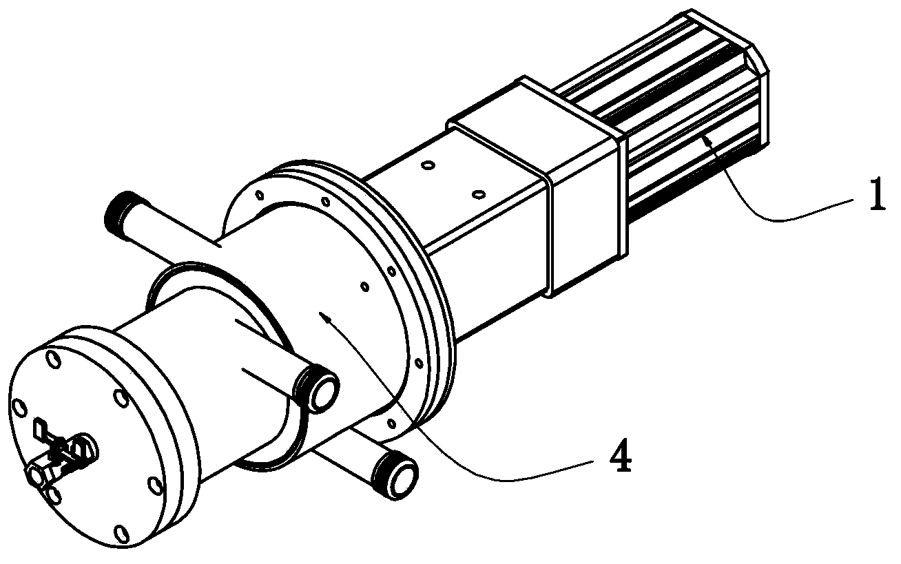
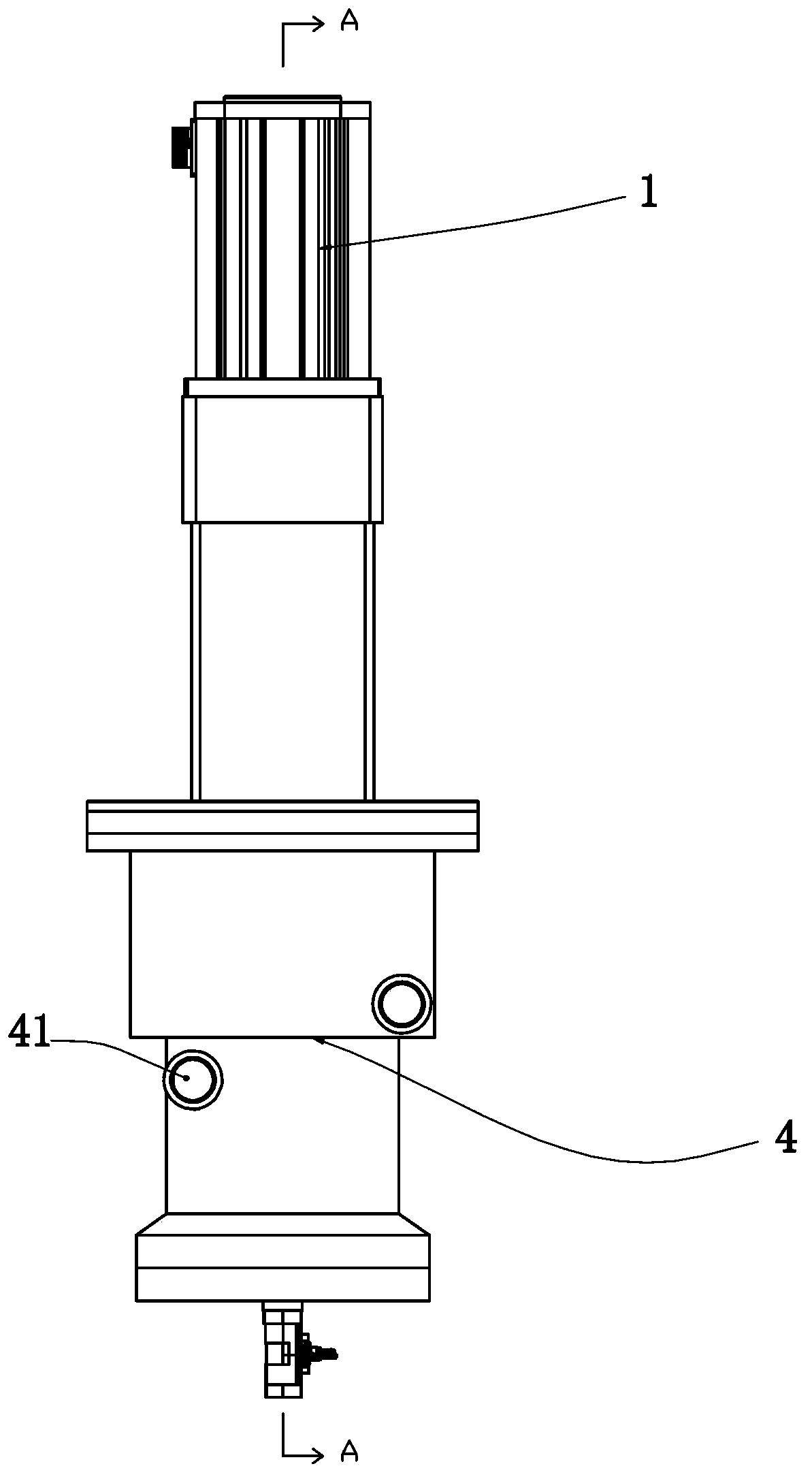
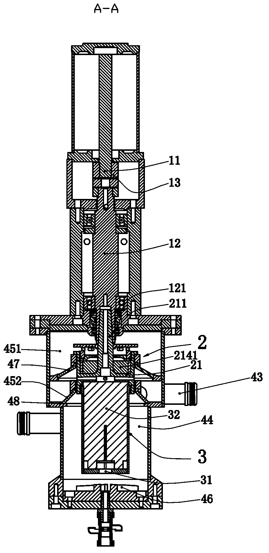
[0039] Such as Figure 1-11 The specific embodiment of the present invention shown includes a motor 1, a guide body assembly 2, a rotating drum 3 and a casing 4, the motor 1 is connected to the guide body 2 by coaxial transmission, and the guide body assembly 2 is connected to the rotating body The drum 3 is fixed and connected by coaxial transmission. The diverter assembly 2 and the drum 3 are both rotatably installed in the casing. The casing 4 is provided with a material inlet 41, a heavy phase outlet 42 and a light phase outlet 43. In this embodiment The material inlet 41 described...


PUM


Abstract

The invention discloses a centrifugal extractor which comprises a motor, a flow deflector assembly, a rotary drum and a housing, wherein the flow deflector assembly comprises a flow deflector that is a centrosymmetric structural body, a baffle is arranged in the flow deflector and divides the flow deflector into an inlet chamber and an outlet chamber, a plurality of light-phase flow deflection holes distributed in a central symmetry manner through taking a rotation axis of the flow deflector as the center are formed in the baffle, inlet ends of the light phase flow deflection holes are communicated with the neighborhood of the center of the inlet chamber, outlet ends of the light phase flow deflection holes penetrates from the flow deflector and are communicated with a light phase outlet, a plurality of first heavy phase flow deflection holes communicated with the inlet chamber and the outlet chamber are formed in the baffle, and the first heavy phase flow deflection holes are distributed in a central symmetry manner through taking the rotation axis of the flow deflector as the center. The centrifugal extractor has a reasonable structural design, is convenient to process accurately by means of overall dynamic balance, and is good in dynamic balance; the flow deflector is less in vibration during the high-speed operation process, the two-phase separation interface is stably controlled, the extraction and separation effect is good, and meanwhile, the centrifugal extractor is also applicable to high-speed extraction and separation of materials difficult to separate.

Description

technical field [0001] The invention relates to a centrifugal extractor. Background technique [0002] Centrifugal extractor is a high-efficiency liquid-liquid extraction equipment designed using the principle of extraction and separation. It is widely used in hydrometallurgy, medicine, fine chemical industry and other fields. The main structure of a traditional centrifugal extractor includes a motor, a diversion body, a drum and a casing. A partition is arranged in the diversion body, and a light-phase diversion hole is arranged under the partition. An axial heavy phase diversion hole is formed, a heavy phase weir is arranged above the diversion body, an axial flow control hole is arranged on the heavy phase weir, and a material inlet, a heavy phase outlet and a light phase outlet are arranged on the shell. Specifically refer to the XS-34 (ring) centrifugal extractor of Ye Chunlin's book, "Cylindrical Centrifugal Extractor" published by Atomic Energy Press. [0003] This...

Claims


Application Information

Patent Timeline
IPC IPC(8): B01D11/04
Inventor 玄浩
Owner 玄浩
Why Eureka
Try Eureka