Planar lightwave circuit and optical receiver

a lightwave circuit and optical receiver technology, applied in the direction of optical elements, multiplex communication, instruments, etc., can solve the problem of difficult adjustment of positional relationships between a plurality of bulk elements

Inactive Publication Date: 2016-03-08
NEC CORP
View PDF15 Cites 3 Cited by
  • Summary
  • Abstract
  • Description
  • Claims
  • Application Information

AI Technical Summary

Benefits of technology

[0019]According to the present invention, it becomes possible to provide a planar lightwave circuit and an optical receiver in which, in a planar lightwave circuit including a 90-degree optical hybrid, the points at which waveguides intersect are decreased, the polarization extinction ratio of the light inputted into the 90-degree optical hybrid is improved, and it is easy to equalize the length of respective optical paths for the signal light and the local oscillation light in the path from the point where the light is split depending on the polarization to the point where the light is inputted into the 90-degree optical hybrid.

Problems solved by technology

However, if the micro-optics technology is used in that way, it is difficult to adjust positional relationships between a plurality of bulk elements.

Method used


Image

  • Planar lightwave circuit and optical receiver
  • Planar lightwave circuit and optical receiver
  • Planar lightwave circuit and optical receiver

Examples


Embodiment Construction

[0025]The exemplary embodiment of the present invention will be described with reference to drawings below.

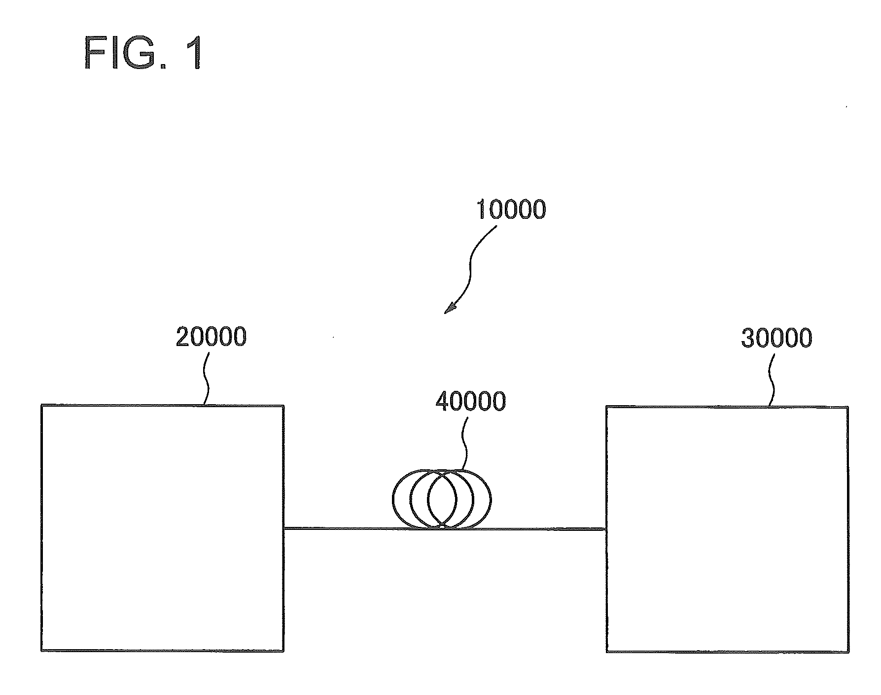
[0026]First, an optical transmission system 10000 will be described using FIG. 1. The optical transmission system 10000 includes an optical transmitter 20000 transmitting signal light modulated by polarization-multiplexed M-level phase modulation (M representing an integer equal to or larger than two), a transmission line 40000 propagating the signal light transmitted by the optical transmitter 20000, and an optical receiver 30000 receiving the signal light through the transmission line 40000.

[0027]A single mode optical fiber can be used as the transmission line 40000, for example.

[0028]The optical receiver 30000 demodulates the signal light and outputs demodulated bit sequence to the outside. An example of a configuration of the optical receiver 30000 will be described using FIG. 5. The demodulation using the digital signal processing will be described as an example.

[0029]The ...


PUM


Abstract

A planar lightwave circuit includes a substrate in which a groove being formed, the groove dividing the substrate into a first area and a second area; a first filter, a second filter, and a third filter intruded into the groove; as are formed in the first area, a first and a second waveguides formed to guide signal light and local oscillation light; a third and a fourth waveguides formed to guide signal light and local oscillation light; a first 90-degree optical hybrid; as are formed in the second area, a fifth and sixth waveguides formed to guide signal light and local oscillation light; and a second 90-degree optical hybrid.

Description

TECHNICAL FIELD[0001]The present invention relates to a planar lightwave circuit and an optical receiver which receive polarization-multiplexed signal light.BACKGROUND ART[0002]With the recent explosive growth in network traffic, ultra-high-speed optical transmission systems of 40 Gbit / s and more than 100 Gbit / s have been investigated. With respect to the ultra-high-speed optical transmission systems, active investigation has been performed on digital coherent communication obtained by combining a phase modulation method with coherent detection and digital signal processing technologies. The phase modulation method has better characteristics required for the long haul optical fiber transmission such as characteristics of the tolerance for signal light noise, chromatic dispersion, and polarization mode dispersion.[0003]As a modulation method, Binary Phase Shift Keying (BPSK) and Quadrature Phase Shift Keying (QPSK) have attracted attention because of their excellent tolerances for th...

Claims


Application Information

Patent Timeline
Patent Type & Authority Patents(United States)
IPC IPC(8): H04J14/00H04B10/60H04B10/61G02B6/42G02B6/10G02B6/12H04B10/25H04J14/06
CPCH04B10/61G02B6/4213G02B6/105G02B6/12004H04B10/25H04B10/60H04J14/06
Inventor YAMAZAKI, HIROYUKI
Owner NEC CORP
Why Eureka
Try Eureka