Check patentability & draft patents in minutes with Patsnap Eureka AI!

Wheel Loader Payload Measurement System Linkage Acceleration Compensation

a payload measurement system and payload technology, applied in the field of payload measurement system, can solve the problems of increasing the maintenance cost of the transport vehicle, causing costly delays, and overloading the transport vehicle,

Active Publication Date: 2017-07-06
CATERPILLAR INC
View PDF12 Cites 24 Cited by
  • Summary
  • Abstract
  • Description
  • Claims
  • Application Information

AI Technical Summary

Benefits of technology

The present patent describes a machine and a method for determining the payload weight of a load of material carried by an implement of the machine. The machine includes a lift arm pivotally connected to an end frame, an implement pivotally connected to the lift arm, and a lift cylinder with a lift cylinder head end pressure sensor and a lift arm angle sensor. The machine also includes a control lever position sensor, a lift arm angle sensor, a head end pressure sensor, and a display device. The controller of the machine detects the control lever position sensor and the lift arm angle sensor, and determines the lift cylinder pressure differential based on the head end pressure and the lift arm angle. The controller also determines the lift arm angular acceleration and the compensated pressure differential by multiplying the lift cylinder pressure differential by the angular acceleration compensation factor. The compensated pressure differential is then used to determine the payload weight of the load of material in the implement. The technical effect of this patent is to provide a more accurate and efficient way to determine the payload weight of a load of material in a machine.

Problems solved by technology

Overloading the transport vehicle, however, may have negative consequences.
Particularly, placing too much weight on a transport vehicle can significantly increase maintenance costs for the transport vehicle or create costly delays if the excess material is removed prior to transport.
Under loading the transport vehicle may also be undesirable if it creates inefficiencies due to added delays and expense required to make additional trips of the transport vehicles to move material around and to remove the material from the work site.

Method used


Image

  • Wheel Loader Payload Measurement System Linkage Acceleration Compensation
  • Wheel Loader Payload Measurement System Linkage Acceleration Compensation
  • Wheel Loader Payload Measurement System Linkage Acceleration Compensation

Examples


Embodiment Construction

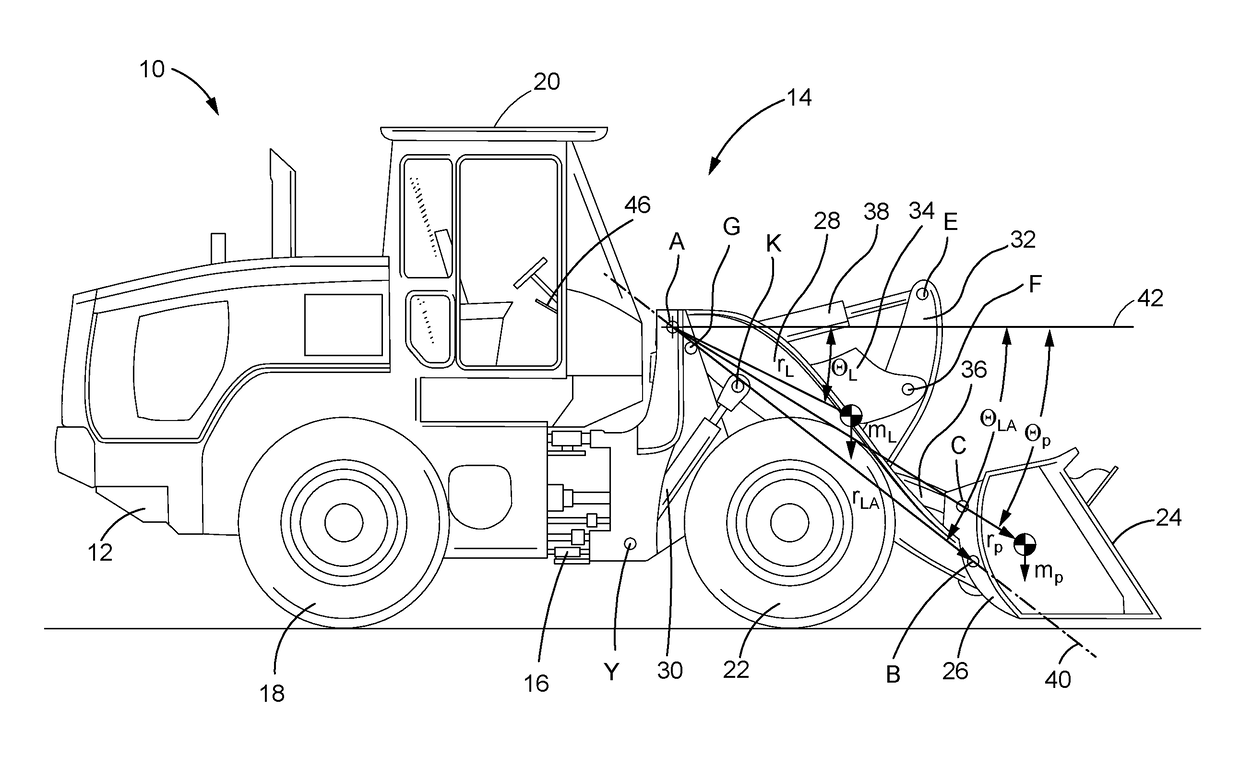
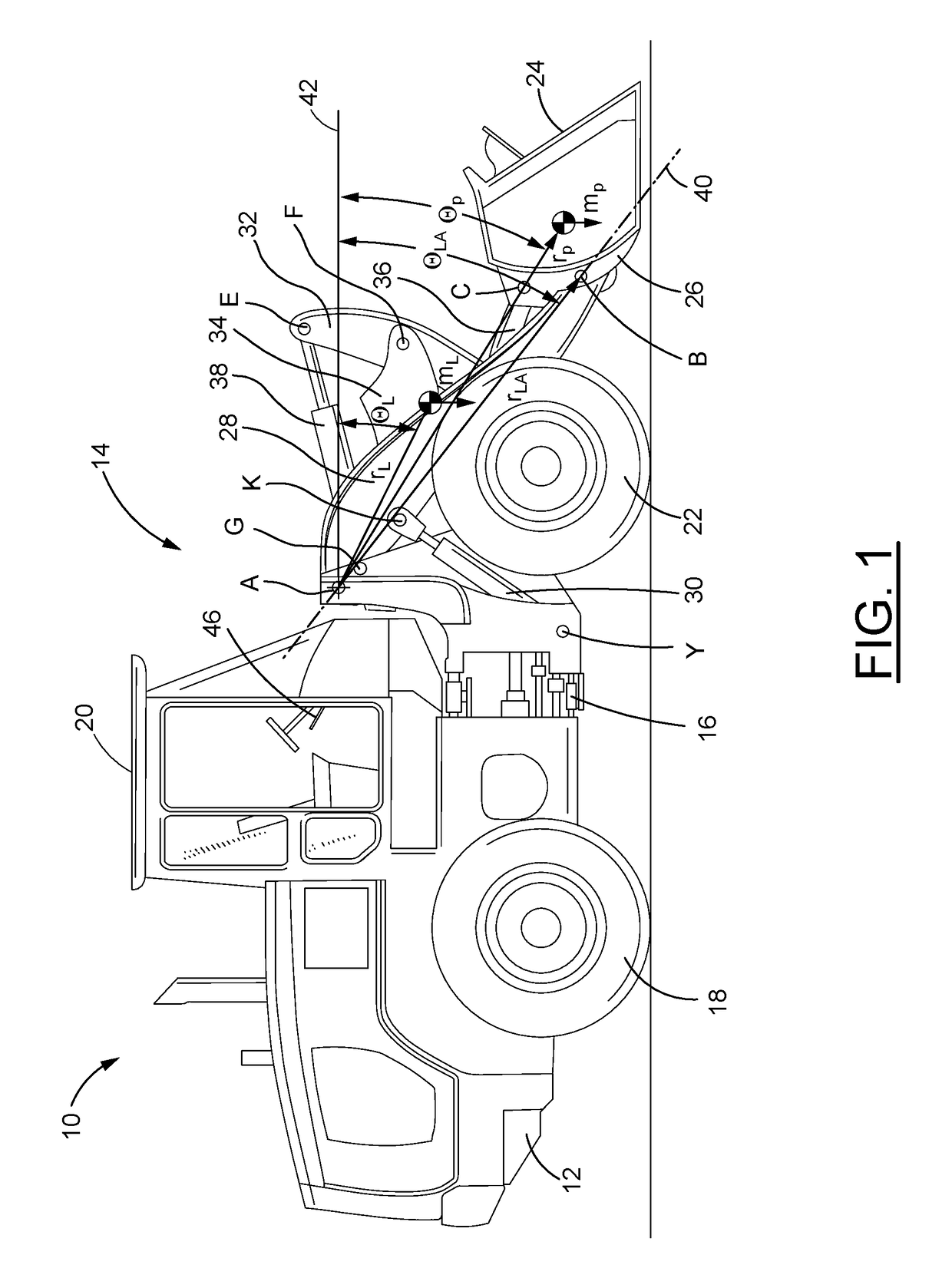
[0015]FIG. 1 illustrates an embodiment of a wheel loader machine 10 in which a payload measurement system in accordance with the present disclosure may be implemented. The wheel loader machine 10 includes a body portion 12 and a non-engine end frame 14 connected by an articulating joint 16. The body portion 12 houses an engine (not shown) that drives rear wheels 18, and includes an elevated cab 20 for the operator. The end frame 14 has front wheels 22 that are turned by a steering mechanism (not shown), with the articulating joint 16 allowing the end frame 14 to move from side-to-side to turn the wheel loader machine 10. In the illustrated embodiment, an implement 24 in the form of a bucket is mounted at the front of the end frame 14 on a coupler 26. The implement 24 and the coupler 26 may be configured for secure attachment of the implement 24 during use of the wheel loader machine 10, and for release of the bucket 24 and substitution of another implement. Although the coupler 26 a...


PUM


Abstract

A payload weight of a load of material carried by an implement of a machine may be estimated taking into account angular acceleration of the payload. A lift cylinder pressure differential and a lift arm angular acceleration may be determined as the implement is raised through a weigh range. An angular acceleration compensation factor may be determined from the lift arm angular acceleration, and a compensated differential pressure may be calculated by multiplying the lift cylinder pressure differential by the angular acceleration compensation factor. The estimated payload weight may then be determined based on the compensated pressure differential and a head end cross-sectional area of the lift cylinder.

Description

TECHNICAL FIELD[0001]The present disclosure relates generally to a payload measurement system and, more particularly, to a payload measurement system that compensates for acceleration of a linkage raising a work implement carrying the payload.BACKGROUND[0002]Various types of machines may use a work implement to transfer material from a work site and load the material onto transport vehicles (e.g., dump trucks, railroad cars and the like). These machines include excavators, wheel loaders, backhoes and other material moving machines. The transport vehicles loaded by the machines may have a particular load capacity determined by a manufacturer's maximum load rating and / or other factors, such as, for example, weight restrictions for on-highway vehicles. To promote maximum utilization of the transport vehicles, it may be desirable to load each transport vehicle as close as possible to its load capacity. Overloading the transport vehicle, however, may have negative consequences. Particula...

Claims


Application Information

Patent Timeline
IPC IPC(8): E02F9/26E02F9/22E02F3/42G01G19/08E02F3/28
CPCE02F9/26G01G19/083E02F9/2203E02F3/422E02F3/283E02F9/264
Inventor SHATTERS, AARON R.CLER, ERIC W.
Owner CATERPILLAR INC
Features
  • R&D
  • Intellectual Property
  • Life Sciences
  • Materials
  • Tech Scout
  • Unparalleled Data Quality
  • Higher Quality Content
  • 60% Fewer Hallucinations
Learn More