

Control device for internal combustion engine
- Summary
- Abstract
- Description
- Claims
- Application Information
AI Technical Summary
Benefits of technology
Problems solved by technology
Method used
Image

Examples
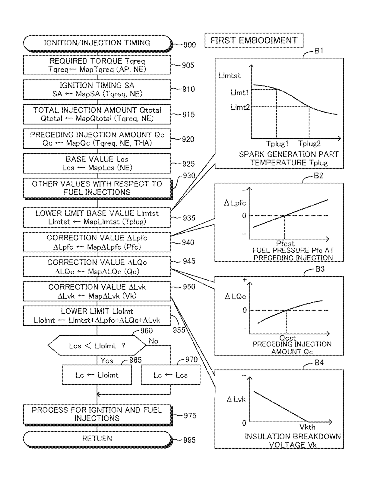
first embodiment
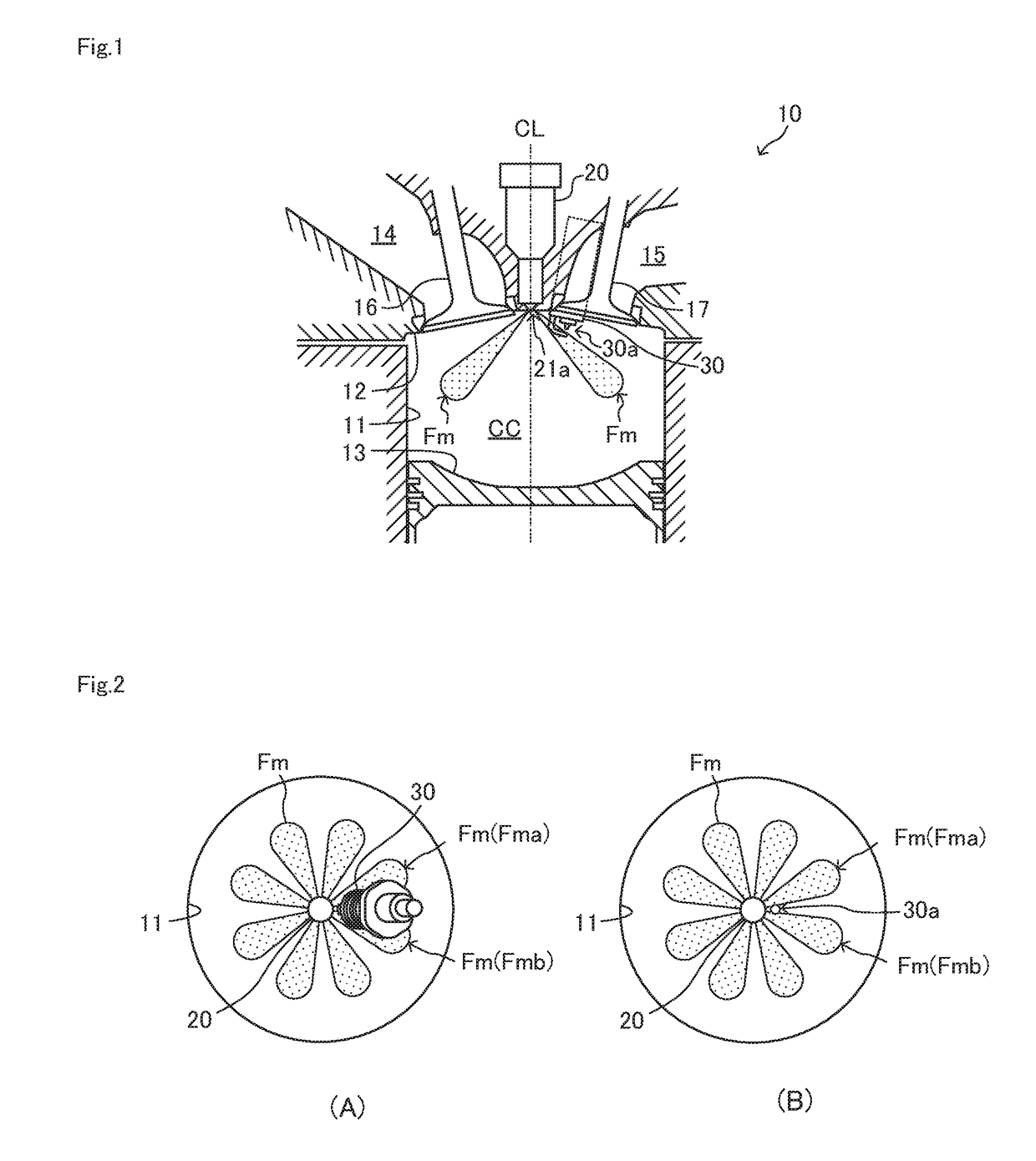
[0062]The control device according to the first embodiment of the invention is applied to the internal combustion engine 10 shown in FIG. 1. Hereinafter, the control device according to the first embodiment will be referred to as “the first device. The engine 10 is a piston-reciprocating cylinder-injection (direct-injection) spark-ignition type of the multi-cylinder (in this embodiment, four-cylinder) gasoline engine. The engine 10 has combustion chambers (cylinders) CC.
[0063]Each of the combustion chambers CC has a generally cylindrical space defined by the cylinder bore wall face (the side wall face of the cylinder) 11, the cylinder head bottom wall face (the combustion chamber upper wall face) 12, the top wall face 13 of the piston, and the intake and exhaust valves 16 and 17 described below.
[0064]Intake and exhaust ports 14 and 15 are formed in the cylinder head part. The ports 14 and 15 communicates with the corresponding combustion chamber CC, respectively. Further, the intake...
second embodiment
[0165]The control device of the engine according to the second embodiment of the invention (hereinafter, this control device may be referred to as “the second device”) is the same as the first device except that the second device changes the lower limit Llolmt in consideration of the influence of the flow of the fuel in the sac chamber Sk of the injector 20 generated by the pre-injection InjB on the preceding injection InjC. Hereinafter, the flow of the fuel remaining in the sac chamber Sk of the injector 20 at the start timing (the injection start timing SOIc) of the preceding injection InjC may be simply referred to as “the sac chamber fuel flow”.
[0166]In particular, the flow of the fuel (the turbulence of the flow of the fuel) occurs in the sac chamber Sk of the injector 20 by the pre-injection InjB. If the preceding injection InjC is carried out under a state that the fuel flow remains in the sac chamber Sk, the spray of the injected fuel easily disperses (the degree of the spre...
third embodiment
[0202]The control device of the engine according to the third embodiment of the invention (hereinafter, this control device may be referred to as “the third device”) changes the minimum value Tmin of the interval Tint with respect to the pre-injection InjB in consideration of the influence of the sac chamber fuel flow on the preceding injection InjC. That is, the third device employs the interval Tint with respect to the pre-injection InjB as the disperse parameter for changing the degree of the spread of the fuel spray formed by the preceding injection InjC.
[0203]When the interval Tint with respect to the pre-injection InjB is limited to the minimum value Tmin, the strength of the sac chamber fuel flow weakens as the minimum value Tmin increases. Therefore, in this case, the degree of the spread of the spray of the fuel injected by the preceding injection InjC decrases and the amount of the fuel adhering to the spark generation part 30a decreases. As a result, the fast increasing o...
PUM
 Abstract
Description
Claims
Application Information