Controlling unmanned aerial vehicles to avoid obstacle collision

a technology collision avoidance, applied in the field of unmanned aerial vehicles, can solve problems such as sensing and computational resources, and achieve the effects of reducing computational costs, simple and efficient, and accurate representation

Active Publication Date: 2017-07-06
CALIFORNIA INST OF TECH
View PDF1 Cites 117 Cited by
  • Summary
  • Abstract
  • Description
  • Claims
  • Application Information

AI Technical Summary

Benefits of technology

[0013]Embodiments of the invention provide a system, framework, and method for controlling the navigation of unmanned vehicles (e.g., configuration flat robots) to avoid obstacle collision in a cluttered environment. Range measurements from multiple sensors are represented compactly and a trajectory is generated in a data structure referred to as an egospace representation. Egospace generalizes depth image obstacle representations. In this regard, egospace uses the natural sensor geometry to combine the benefits of a multi-resolution and multi-sensor representation architecture into a single, simple, and efficient layer. With the egospace representation, motion planning over full configuration flat dynamics is conducted using motion primitives expressed directly in egospace coordinates or by direct forward integration of a vehicle model also expressed in the egospace coordinates. The motion planning output is then used to determine inputs that control the configuration flat dynamics to follow a trackable path.
[0014]Further embodiments of the invention provide the ability to perform temporal fusion on the depth maps resulting from the range measurements. In particular, each pixel of a depth map is represented by a mixture of Gaussian inverse-depth models. Consecutive frames are related to each other by transformations obtained from visual odometry. The result provides a more accurate representation than alternative image space depth map fusion techniques at a lower computational cost.

Problems solved by technology

Micro air vehicles (MAVs) are a challenging UAV platform for high-speed autonomous flight in cluttered environments because their power and size restrictions severely limit the sensing and computational resources that can be carried onboard.

Method used


Image

  • Controlling unmanned aerial vehicles to avoid obstacle collision
  • Controlling unmanned aerial vehicles to avoid obstacle collision
  • Controlling unmanned aerial vehicles to avoid obstacle collision

Examples


Embodiment Construction

[0026]In the following description, reference is made to the accompanying drawings which form a part hereof, and which is shown, by way of illustration, several embodiments of the present invention. It is understood that other embodiments may be utilized and structural changes may be made without departing from the scope of the present invention.

Overview

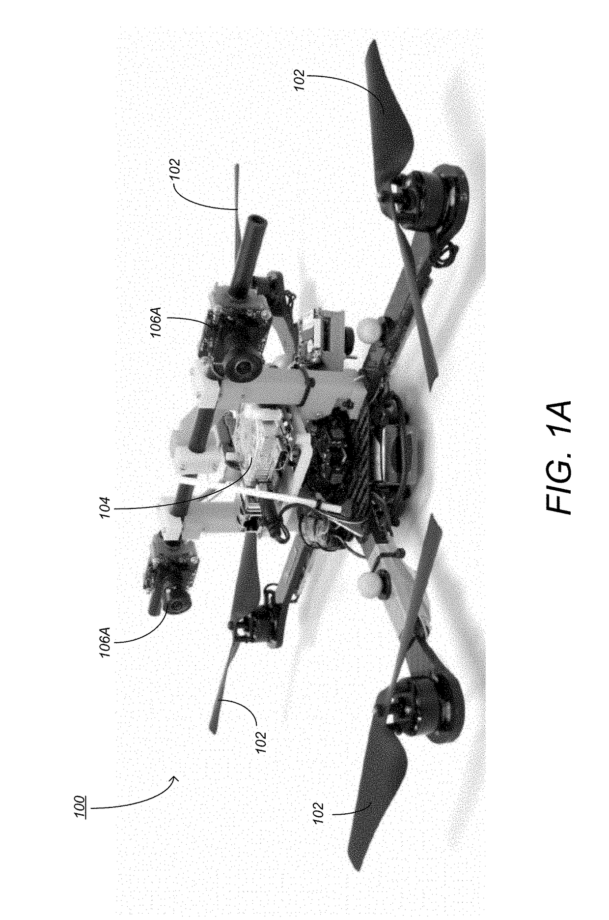
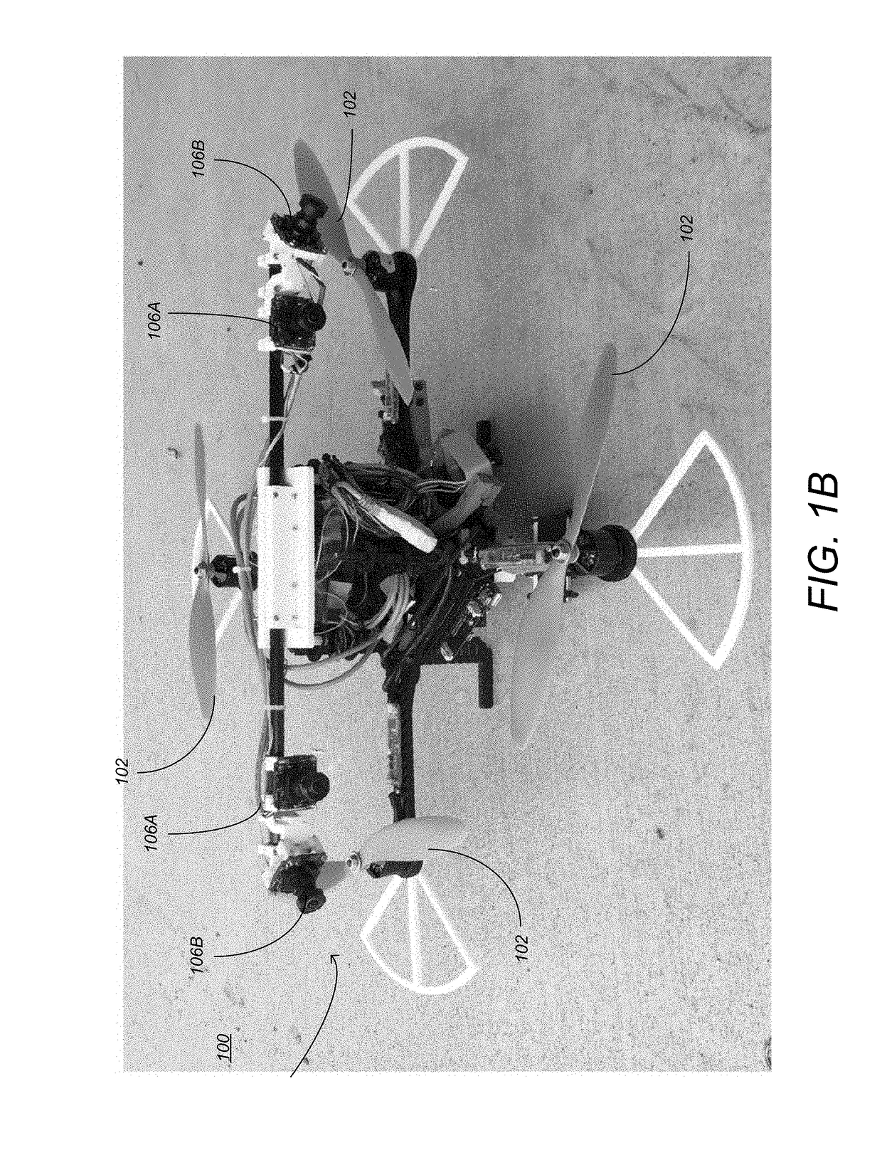
[0027]Embodiments of the invention provide a pipeline for avoiding obstacles at high speeds, using an arbitrary suite or range sensors, for robotic aircraft (“unmanned aerial vehicles”) that satisfy the “configuration flat” property (see below), including those of a small, portable size known as micro air vehicles (MAVs). Embodiments may be utilized in / by aircraft of the multirotor family, which include the widely available quadcopter platform (also referred to as a “quadrotor” or, colloquially, as a “drone”). Embodiments may be utilized in / by aircraft of the fixed-wing family, which includes airplane-like platforms. The ability to f...


PUM


Abstract

A method, device, framework, and system provide the ability to control an unmanned aerial vehicle (UAV) to avoid obstacle collision. Range data of a real-world scene is acquired using range sensors (that provide depth data to visible objects). The range data is combined into an egospace representation (consisting of pixels in egospace). An apparent size of each of the visible objects is expanded based on a dimension of the UAV. An assigned destination in the real world scene based on world space is received and transformed into egospace coordinates in egospace. A trackable path from the UAV to the assigned destination through egospace that avoids collision with the visible objects (based on the expanded apparent sizes of each of the visible objects) is generated. Inputs that control the UAV to follow the trackable path are identified.

Description

CROSS-REFERENCE TO RELATED APPLICATIONS[0001]This application claims the benefit under 35 U.S.C. Section 119(e) of the following co-pending and commonly-assigned U.S. provisional patent application(s), which is / are incorporated by reference herein:[0002]Provisional Application Ser. No. 62 / 274,924, filed on Jan. 5, 2016, with inventor(s) Roland Brockers, Stephan M. Weiss, Larry H. Matthies, and Anthony T. Fragoso, entitled “Fast Autonomous Obstacle Avoidance for Micro Air Vehicle Flight in Highly Cluttered Environments,” attorneys' docket number 176.126-US-P1; and[0003]Provisional Application Ser. No. 62 / 397,284, filed on Sep. 20, 2016, with inventor(s) Anthony T. Fragoso, Larry H. Matthies, and Richard M. Murray, entitled “Fast Motion Planning Representation for Micro Air Vehicles,” attorneys' docket number 176.126-US-P2.STATEMENT REGARDING FEDERALLY SPONSORED RESEARCH AND DEVELOPMENT[0004]The invention described herein was made in the performance of work under NASA Contract NNN12AA...

Claims


Application Information

Patent Timeline
Patent Type & Authority Applications(United States)
IPC IPC(8): G08G5/00G05D1/02G01C21/00G05D1/00G06V20/00G06V20/13
CPCG08G5/0069G05D1/0011G05D1/0202G08G5/045G01C21/005G08G5/0034G08G5/0073G05D1/102G01S17/89G01S17/933B64C39/024G01S17/86G06V20/00G06V20/13G06V10/751B64U2101/00B64U2101/30B64U2201/10
Inventor FRAGOSO, ANTHONY T. S.MATTHIES, LARRY H.BROCKERS, ROLANDMURRAY, RICHARD M.
Owner CALIFORNIA INST OF TECH
Why Eureka
Try Eureka