Systems and methods for providing an enhanced audible environment within an aircraft cabin

a technology of enhanced audible environment and aircraft cabin, which is applied in the direction of transducer details, electrical transducers, instruments, etc., can solve the problems of poor sound quality, acoustic transducers, and few commercial success stories, so as to facilitate sound transmission and improve the audible environment

Inactive Publication Date: 2017-07-06
BONGIOVI ACOUSTICS LLC
View PDF6 Cites 21 Cited by
  • Summary
  • Abstract
  • Description
  • Claims
  • Application Information

AI Technical Summary

Benefits of technology

[0012]Certain embodiments of the present invention also incorporate implementation of transducers within an aircraft cabin to improve the audible environment within. Accordingly, transducers may be applied to panels, bulkheads, walls, and / or windows within the aircraft to facilitate transmission of sounds, such as PA announcements, or, in particular embodiments, active noise cancellation. Such embodiments may be deployed in conjunction with microphones, receiver modules, and processor modules, to produce appropriate signals for driving the transducers so as to produce the desired audible environment within the aircraft cabin.

Problems solved by technology

However, although surface transducers have been known for some time, few have ever achieved commercial success due to the technical limitations of these transducers, and the resulting poor quality of sound by merely attaching the transducers to various surfaces.
Specifically, one limitation of surface acoustic transducers is due to the lack of a mechanical excursion, which causes an absence of highs and lows in sound frequency.
For example, rather than achieving a rich bass sound, regular surface acoustic transducers have limited frequency response resulting in a lower quality narrow band response as compared to traditional loudspeakers.
Another issue with surface transducers is the effect of the attached bracket surface or external housing for mounting the surface transducers.
That is, structurally, current surface mounted transducers do not account for movement or variation to the vibrational surface which the surface transducer is attached to.
For example, a person leaning against a wall or surface to which the surface transducer is attached to would have a drastic impact on the sound or sound quality being reproduced due to potential deflection of the transducer onto adjacent surfaces behind the application.

Method used


Image

  • Systems and methods for providing an enhanced audible environment within an aircraft cabin
  • Systems and methods for providing an enhanced audible environment within an aircraft cabin
  • Systems and methods for providing an enhanced audible environment within an aircraft cabin

Examples


Embodiment Construction

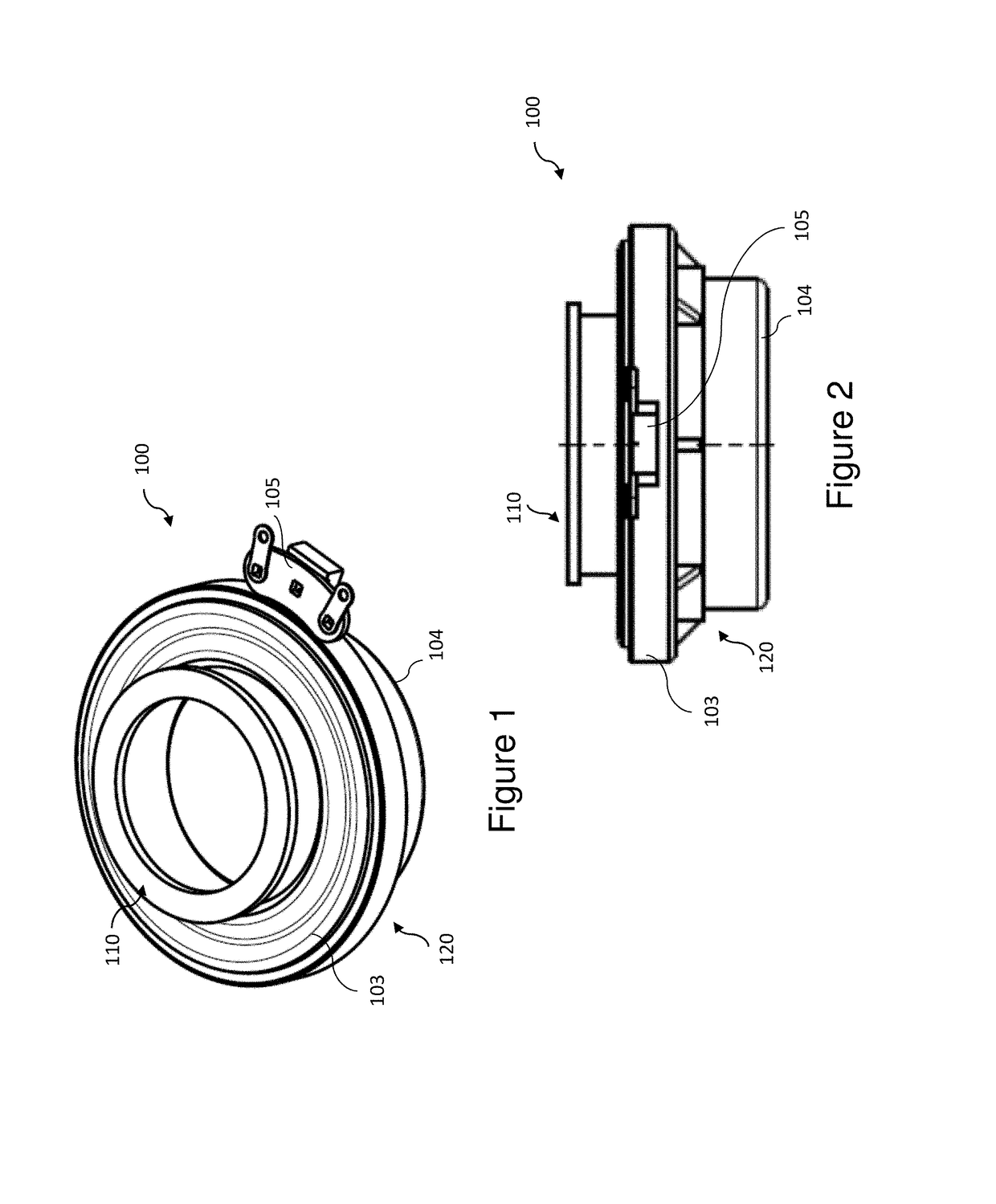
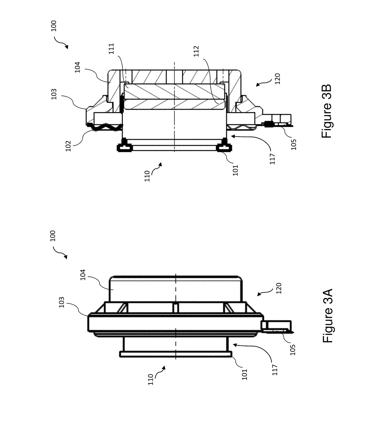
[0037]As illustrated by the accompanying drawings, the present invention is directed to a surface acoustic transducer. In a preferred embodiment, the surface acoustic transducer of the present invention is optimally structured, as described below, for producing high quality sound within an aircraft cabin by vibrating its interior cabin walls, bulkheads, and / or windows. Of course, the present surface acoustic transducer may also be utilized to vibrate other surfaces. Specifically, the surface acoustic transducer of the present invention includes a transducer housing structured to at least partially enclose a primary assembly having a voice coil assembly and a magnet. In an embodiment, the transducer housing may further be mounted within an external housing or mounting bracket having a rigid retaining wall and an excursion cover. This excursion cover may be formed of a malleable helix structure such as to protect the surface acoustic transducer from external disturbance, yet at the sa...


PUM


Abstract

A system for providing an enhanced audible environment within an aircraft cabin includes at least one, but possibly, a plurality of transducers mounted symmetrically about a window of the aircraft cabin on a mounting flange of the window. The transducers are cooperatively disposed and configured to excite at least a viewing pane of said window so as to provide a desired audible environment within an aircraft cabin, without obstructing the view from the window.

Description

CLAIM OF PRIORITY[0001]The present application is a continuation-in-part application of previously filed, now pending application having Ser. No. 14 / 942,569, filed on Nov. 16, 2015 incorporated herein by reference.FIELD OF THE INVENTION[0002]The present invention provides for systems and methods associated with surface acoustic transducers optimally structured for an aircraft cabin and improving the audible environment within.BACKGROUND OF THE INVENTION[0003]Where traditional loud speakers create sound by converting electric signals into mechanical motion in order to vibrate a diaphragm or cone, surface acoustic transducers operate to produce sound without a cone. That is, a surface acoustic transducer operates by attachment to a surface, such as an existing panel or wall made of various materials, and directing vibrations directly onto the surface in order to create sound.[0004]Surface acoustic transducers are generally known in the art. For instance, a surface acoustic transducer ...

Claims


Application Information

Patent Timeline
Patent Type & Authority Applications(United States)
IPC IPC(8): G10K11/178
CPCG10K11/1788G10K2210/3229G10K2210/1281G10K11/1786G10K11/004H04R1/028H04R1/227H04R7/04H04R9/063H04R27/00H04R2499/13G10K11/1787G10K11/17857G10K11/17875
Inventor BONGIOVI, ANTHONYHAMELINK, LAWRENCE ROBERTSERVIS, BRIAN K.BIELSKI, JOHN ROBERT
Owner BONGIOVI ACOUSTICS LLC
Why Eureka
Try Eureka