
Wire terminal assembly and adapter kit

a wire terminal and adapter kit technology, applied in the manufacture of contact parts, coupling device details, coupling device connections, etc., can solve the problems of limited space for connecting wires, difficulty in properly wrapping and twisting, and difficult field connection of sires

Active Publication Date: 2017-07-06
HUBBELL INC
View PDF1 Cites 0 Cited by
  • Summary
  • Abstract
  • Description
  • Claims
  • Application Information

AI Technical Summary

Benefits of technology

The present invention provides an electrical connector assembly that can easily attach to an existing electrical connector or receptacle to accommodate multiple wires to a single terminal or contact without the need for additional jumping of wires or connectors. The assembly includes a plurality of electrical terminal connectors that can be attached to the existing connectors or terminals of the wiring device. Each connector has a clamp member with a threaded aperture for receiving a coupling screw, allowing for clamping of two wires between the connector and clamp member using a single screw. The assembly also includes a cover for guiding and protecting the wires, with an access hole for accessing the screw to tighten it securely. This invention provides an improved solution for wiring multiple devices safely and efficiently.

Problems solved by technology

The housing of the wiring device typically has limited internal space for the wires and the connectors that can make connecting the sires difficult in the field.
The limited space and construction of the housing presents difficulty in properly wrapping and twisting wire in a manner to ensure secure attachment by the screw.
The switches of this form also have limited space for connecting wires and do not permit connecting more than one wire to a single connector.
While connectors for this general purpose have been devised previously, such connectors are generally complicated and expensive to produce.
The wiring devices, such as receptacles, for use in hazardous locations typically do not have space available for multiple wires and connectors.
The receptacles are generally not suitable, or tested and certified for double wiring of the terminals and can increase the problems associated with loosening of the wires during use, which can lead to undesired and dangerous arcing.

Method used


Image

  • Wire terminal assembly and adapter kit
  • Wire terminal assembly and adapter kit
  • Wire terminal assembly and adapter kit

Examples


Embodiment Construction

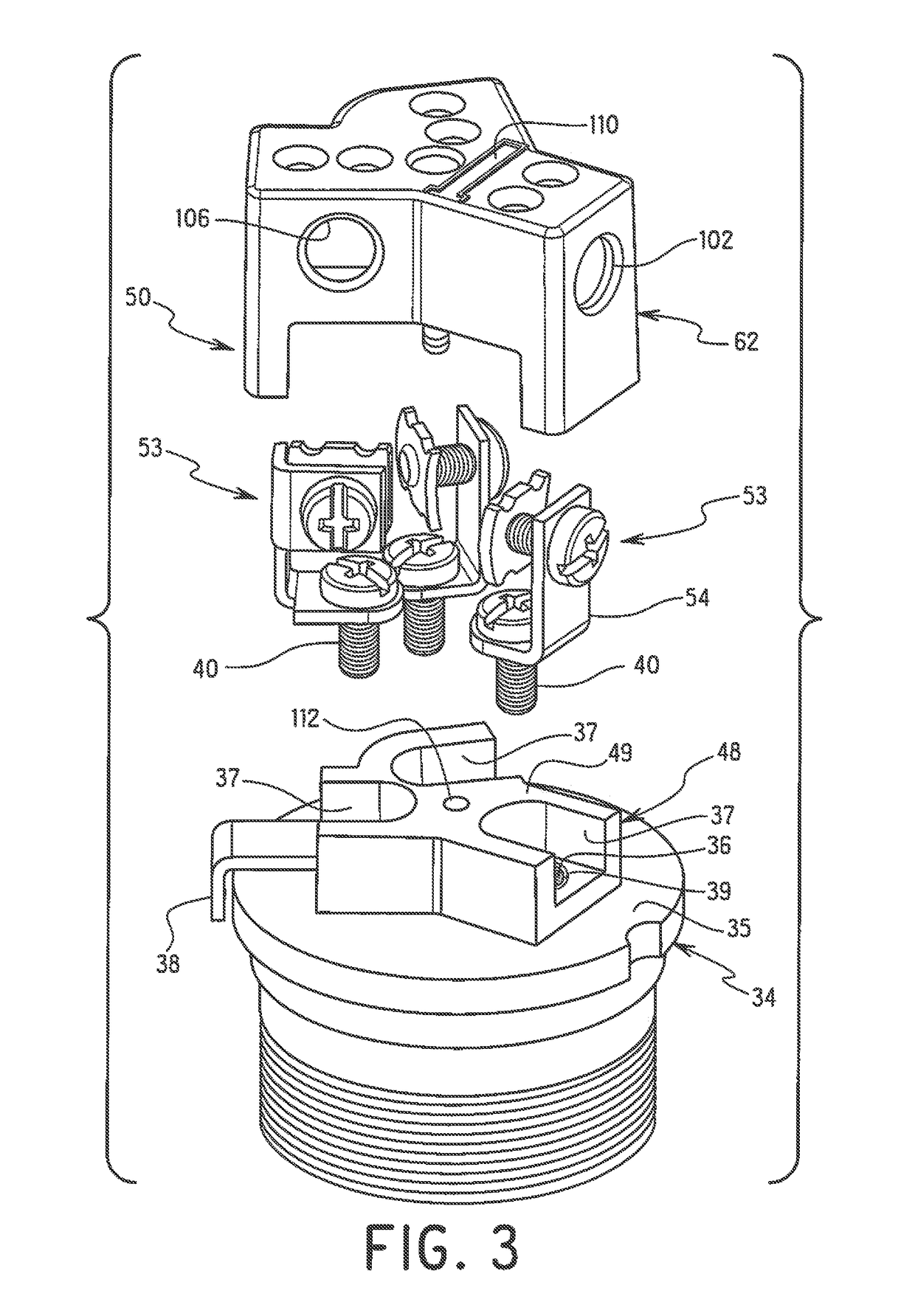
[0037]The invention is directed to an electrical assembly for coupling a plurality of wires to an electrical wiring device. The invention is also directed to an electrical wiring device having electrical terminals and terminal connectors for coupling one or two electrical wires directly to each of the electrical terminals of the electrical wiring device. The invention is further directed to an electrical assembly for modifying an electrical wiring device to receive a plurality of wires and enabling secure attachment of at least two wires to each of the terminals or connectors of the electrical device. The ability to attach two wires securely to the terminal connectors allows multiple wiring devices to be connected together. The electrical assembly can be in the form of a kit containing the terminal connectors, screws, clamping members and cover member for connecting to the electrical wiring device.

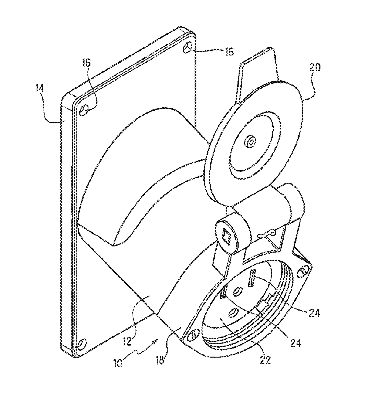
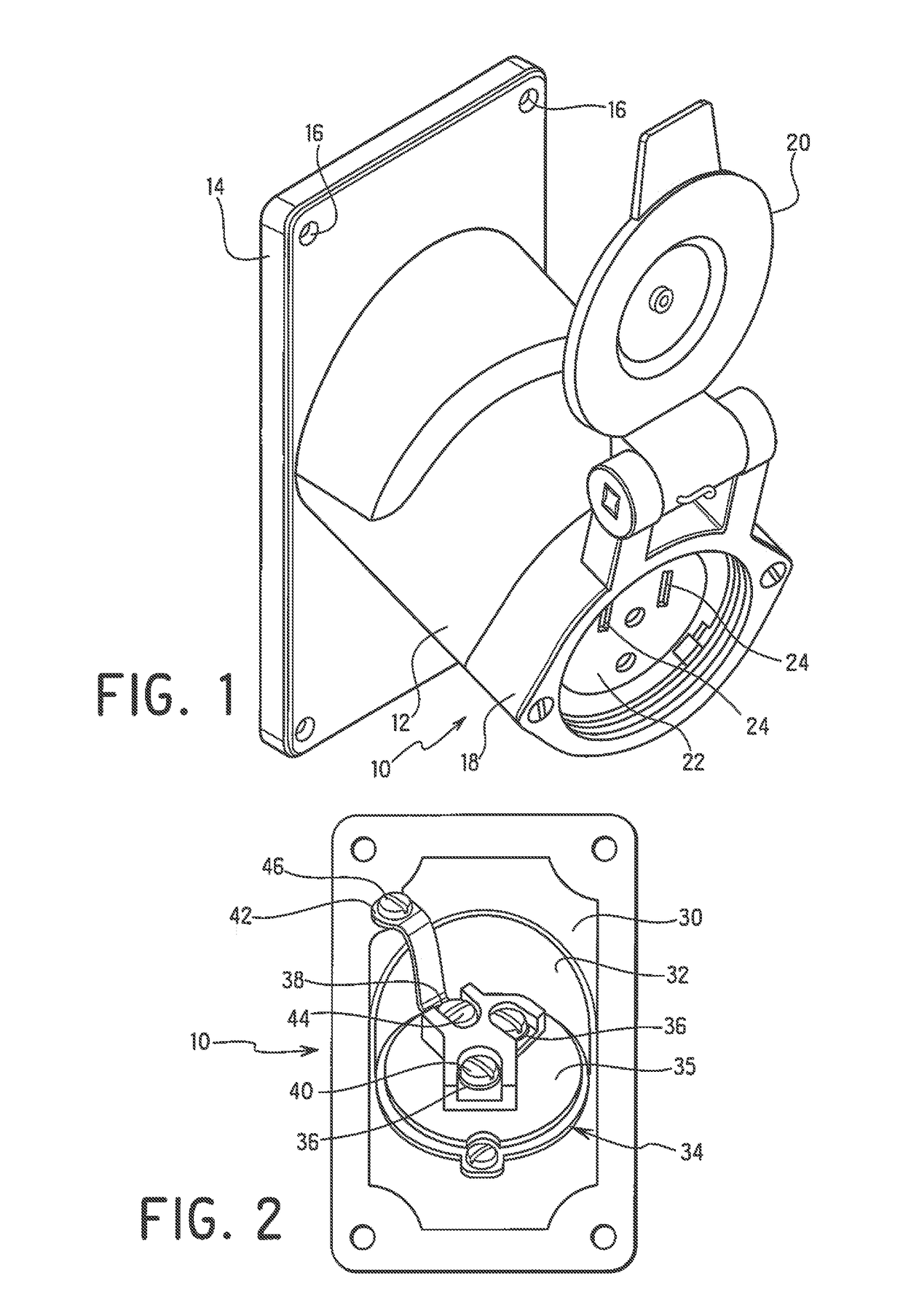
[0038]Referring to FIG. 1, one example of an electrical connector is an electrical wir...


PUM


Abstract

An assembly is provided for a connector of an electrical wiring device having a base with a plurality of electrical terminals having a connecting screw. The assembly includes a plurality of terminal connector with a base extending from the first end and having a screw hole for coupling to one of the electrical terminals by a connecting screw. The leg has a screw hole receiving a coupling screw for electrically connecting a wire to the terminal connector and the terminal of the electrical wiring device. A clamping member receives the coupling screw for clamping the wire between the leg and clamping member. A cover encloses the terminal connectors and includes one or more apertures directing a wire through the cover to the terminal connector assembly to clamp the wire in place. Access openings are provided in a wall of the cover to access the coupling screws for clamping wires to the terminal connector assembly.

Description

[0001]This application is a continuation of U.S. application Ser. No. 14 / 881,838 filed Oct. 13, 2015 which claims the benefit under 35 USC 119(e) of U.S. Provisional Application No. 62 / 064,554 filed Oct. 16, 2014, which is hereby incorporated by reference in its entirety.FIELD OF THE INVENTION[0002]The present invention relates generally to a wire terminal connector for an electrical wiring device for enabling multiple wires to be coupled to each terminal connector of the wiring device. The invention is also directed to a wiring adapter kit for modifying or retrofitting an electrical wiring device in the field to allow multiple wires to be coupled to each electrical terminal connector of the wiring device.BACKGROUND OF THE INVENTION[0003]Electrical connectors, outlets, switches and other wiring devices are commonly used in hazardous and non-hazardous locations. Electrical wiring devices for hazardous locations typically have enclosed housings to protect the internal components. The ...

Claims


Application Information

Patent Timeline
Patent Type & Authority Applications(United States)
IPC IPC(8): H01R4/34H01R13/512H01R43/00H01R24/78H01R13/52
CPCH01R4/34H01R24/78H01R2103/00H01R43/00H01R13/512H01R13/5213H01R4/307H01R24/28H01R43/16H01R2107/00
Inventor STROM, BRENT S.
Owner HUBBELL INC
Learn More