
Optical blood pressure detection device and operating method thereof

a detection device and optical technology, applied in the field of optical blood pressure detection devices, can solve the problems of not reflecting all conditions, e.g., sleep blood pressure, and hemadynamometers that only perform passive measurements, and achieve the effect of stable average blood pressur

Inactive Publication Date: 2017-07-13
PIXART IMAGING INC
View PDF7 Cites 8 Cited by
  • Summary
  • Abstract
  • Description
  • Claims
  • Application Information

AI Technical Summary

Benefits of technology

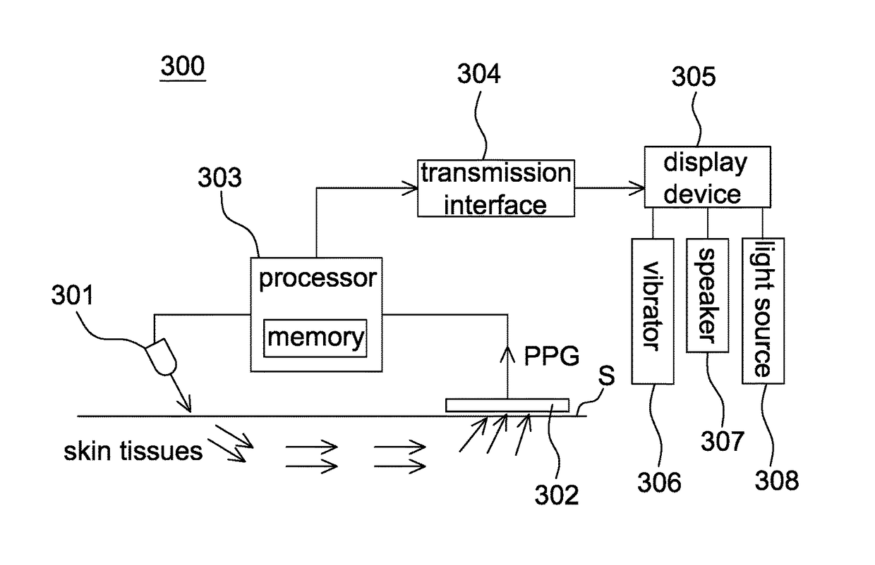
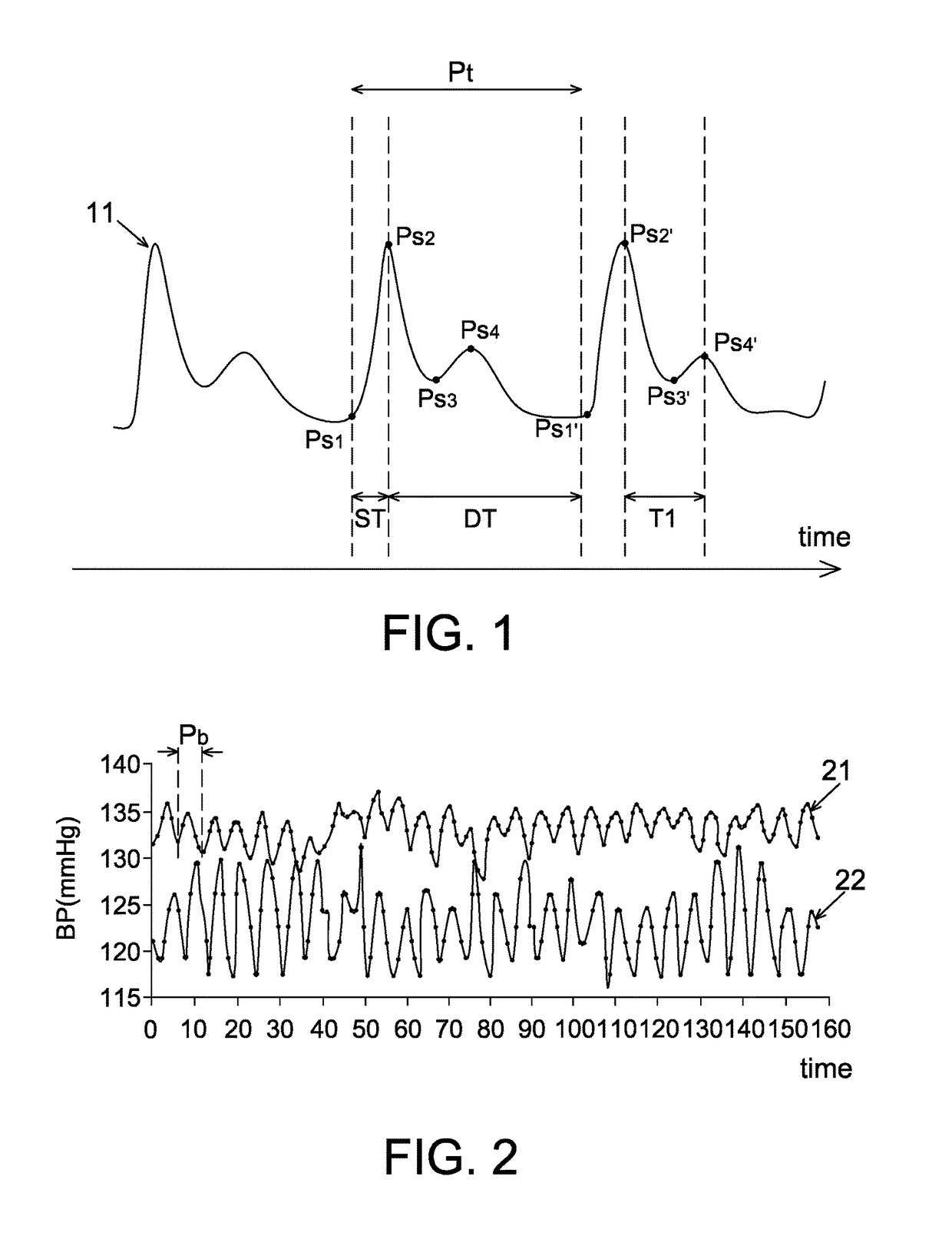
The present invention is about an optical blood pressure detection device and an operating method that can measure the user's blood pressure and respiration rate using a photoplethysmography (PPG) signal. The device includes a light source, a light sensor, and a processor. The processor calculates one or more blood pressures for each pulse duration based on a blood pressure estimation model and a time difference between two feature points within one pulse duration. The device also calculates the user's respiration cycle and averages multiple blood pressures within that cycle to generate an average blood pressure. This average blood pressure is used to calibrate the measured blood pressure. The device's operating method includes the steps of obtaining a PPG signal, calculating blood pressures, and averaging blood pressures within a respiration cycle. The technical effect of this invention is to provide an accurate and non-invasive way to measure blood pressure and respiration rates.

Problems solved by technology

In addition, the conventional hemadynamometer can only perform the passive measurement but is unable to perform so-called active measurement continuously.
Accordingly, detected values of the conventional hemadynamometer are blood pressures only for particular conditions (e.g., the emotion and movement of a user having no significant change for a period of time), but can not truly reflect all conditions, e.g., sleep blood pressures.

Method used


Image

  • Optical blood pressure detection device and operating method thereof
  • Optical blood pressure detection device and operating method thereof
  • Optical blood pressure detection device and operating method thereof

Examples


Embodiment Construction

[0019]It should be noted that, wherever possible, the same reference numbers will be used throughout the drawings to refer to the same or like parts.

[0020]A photoplethysmography (PPG) signal is consisted of two parts. When a systole occurs, the pressure and the blood volume in blood vessels of the whole body have a continuous variation. When a diastole occurs, said pressure decreases correspondingly, and the blood pumped-out in a previous systole heats the heart valve to cause so-called inflection.

[0021]Therefore, a complete PPG waveform includes a mixed effect of systole and the pressure from blood vessel walls. The PPG signal is obtainable by detecting a volume variation of blood vessels through optical measurements.

[0022]To obtain breathing signals and blood pressure signals of a user from a PPG signal, it is necessary to acquire the PPG signal at first. The blood pressure corresponding to each pulse duration (e.g., Pt in FIG. 1) of the PPG signal is then calculated using a blood...


PUM


Abstract

A blood pressure detection method includes the steps of: acquiring a PPG signal from a skin surface using a light sensing element; calculating a blood pressure corresponding to each pulse duration according to at least one pressure estimation model and a time difference between two feature points within one pulse duration; calculating a breathing period; averaging a plurality of blood pressures within the breathing period to generate an average blood pressure; and showing the average blood pressure with a display device.

Description

CROSS REFERENCE TO RELATED APPLICATION[0001]This application claims the priority benefit of Taiwan Patent Application Serial Number 105100804, filed on Jan. 12, 2016, the full disclosure of which is incorporated herein by reference.BACKGROUND[0002]1. Field of the Disclosure[0003]This disclosure generally relates to a blood pressure detection device and, more particularly, to an optical blood pressure detection device based on photoplethysmography (PPG) signals and an operating method thereof[0004]2. Description of the Related Art[0005]Conventionally, to obtain more reliable detected values using a hemadynamometer, it is necessary to repeatedly measure blood pressures for a longer time by the hemadynamometer. In addition, the conventional hemadynamometer can only perform the passive measurement but is unable to perform so-called active measurement continuously. Accordingly, detected values of the conventional hemadynamometer are blood pressures only for particular conditions (e.g., t...

Claims


Application Information

Patent Timeline
Patent Type & Authority Applications(United States)
IPC IPC(8): A61B5/021A61B5/08A61B5/00
CPCA61B5/02125A61B5/0082A61B5/6831A61B5/7257A61B5/0816A61B5/7239A61B5/02416
Inventor HAN, WEI-RUGU, REN-HAUCHUANG, CHIH-YUAN
Owner PIXART IMAGING INC
Learn More