Liquid Discharge Apparatus and Method for Wiping Liquid Discharge Head

Active Publication Date: 2017-07-13
SEIKO EPSON CORP
View PDF1 Cites 0 Cited by
  • Summary
  • Abstract
  • Description
  • Claims
  • Application Information

AI Technical Summary

Benefits of technology

The patent describes a liquid discharge apparatus that includes a wiper and nozzles for discharging liquid. The wiper moves over a wiping surface and is designed to wipe off any stains. The distance between the edge of the wiping surface and the nozzle is shorter on the side with fewer stains and longer on the side with more stains. This allows for effective wiping without rubbing foreign substances into the nozzles and degrading the ink discharge performance. The technical effect of this design is improved ink discharge performance and reduced likelihood of nozzle degradation.

Problems solved by technology

Further, when viscosity of the attached ink is increased, there is a problem in that a discharge direction of ink droplets becomes unstable or a problem in that it is difficult to appropriately discharge ink droplets.
For example, there is a concern that the stain remaining in the region, in which no nozzles are arranged, will fall on a recording medium at an unexpected timing and the recording medium is stained.
In addition, there is also another concern that the stains will be accumulated in the region in which no nozzles are arranged and the recording medium will come into contact with the accumulated stains and will be stained.
In other words, there is a concern that, since stains remain on a part of the line head on the side on which the nozzle surfaces are arranged (the region in which no nozzles are arranged), the recording medium will be stained and the print quality will be degraded.
For example, when the wiping is performed on the wiping surface by causing the wiper to move from the portion having a large number of attachment of the stains toward the portion having a small number of attachment of the stains, a large amount of the stains (foreign substances) moves along with the wiper, the foreign substances are rubbed into the inside of the nozzles, and there is a concern that a problem of degradation of an ink discharge performance of the nozzles will arise.
When the wiper is caused to move from the portion having a small number of attachment of the stains toward the portion having a large number of attachment of the stains, a small amount of the stains (foreign substances) moves along with the wiper, the foreign substances are unlikely to be rubbed into the inside of the nozzles, and a problem of the degradation of the ink discharge performance of the nozzles is unlikely to arise, compared to a case where the wiper is caused to move from the portion having a large number of attachment of the stains toward the portion having a small number of attachment of the stains.
Therefore, the concentrations of the aqueous solvent component in the liquid having the low humectant content rate are different between the region in which the residue of the liquid occurs from the wiping and the region in which the residue of the liquid does not occur from the wiping, and it is difficult to evenly discharge the liquid having the low humectant content rate from the nozzles.
Since the liquid having the high viscosity is more difficult to flow than the liquid having the low viscosity, the liquid having the high viscosity that is attached to the wiping surface is more difficult to be removed through the wiping process than the liquid having the low viscosity that is attached to the wiping surface.
Since the nozzles are arranged to be closer to one side of the wiping surface, a distance between an edge of the wiping surface and the nozzle is not uniform, and there are a portion having a long distance between the edge of the wiping surface and the nozzle and a portion having short distance between the edge of the wiping surface and the nozzle.
Accordingly, when the wiper is caused to move from the portion having a small number of attachment of the stains toward the portion having a large number of attachment of the stains, a small amount of the stains (foreign substances) moves along with the wiper, the foreign substances are unlikely to be rubbed into the inside of the nozzles, and a problem of the degradation of the ink discharge performance of the nozzles is unlikely to arise, compared to a case where the wiper is caused to move from the portion having a large number of attachment of the stains toward the portion having a small number of attachment of the stains.

Method used


Image

  • Liquid Discharge Apparatus and Method for Wiping Liquid Discharge Head
  • Liquid Discharge Apparatus and Method for Wiping Liquid Discharge Head
  • Liquid Discharge Apparatus and Method for Wiping Liquid Discharge Head

Examples


embodiment 1

[0063]Overview of Printer

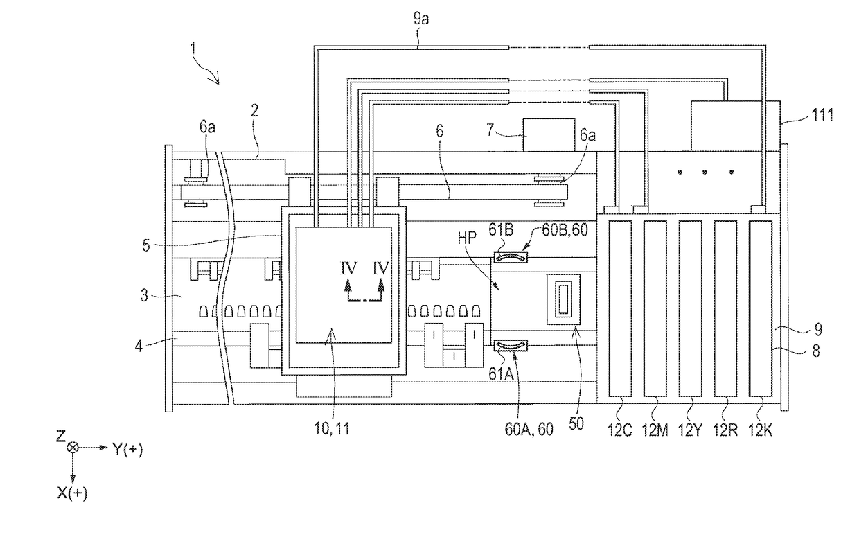
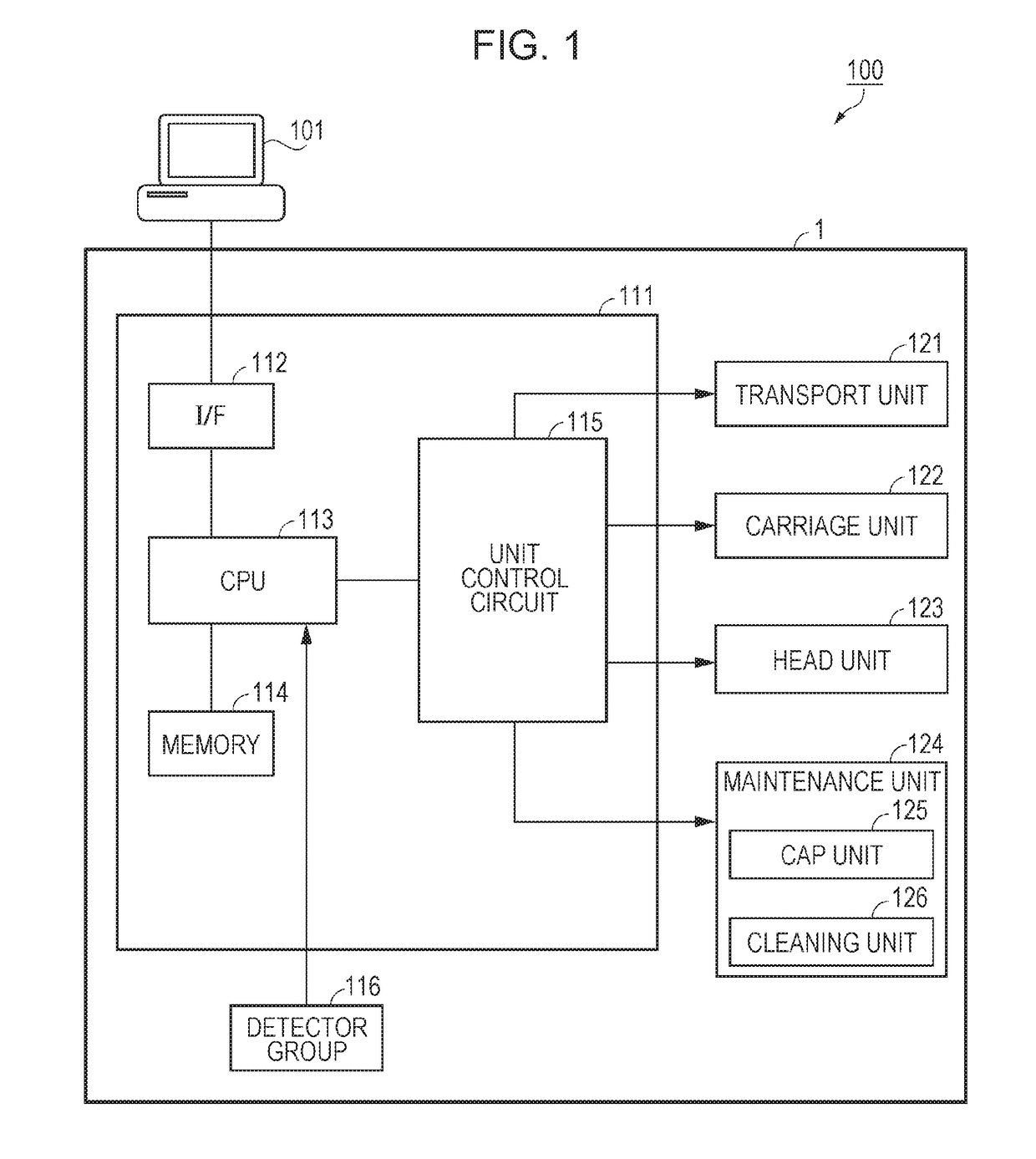
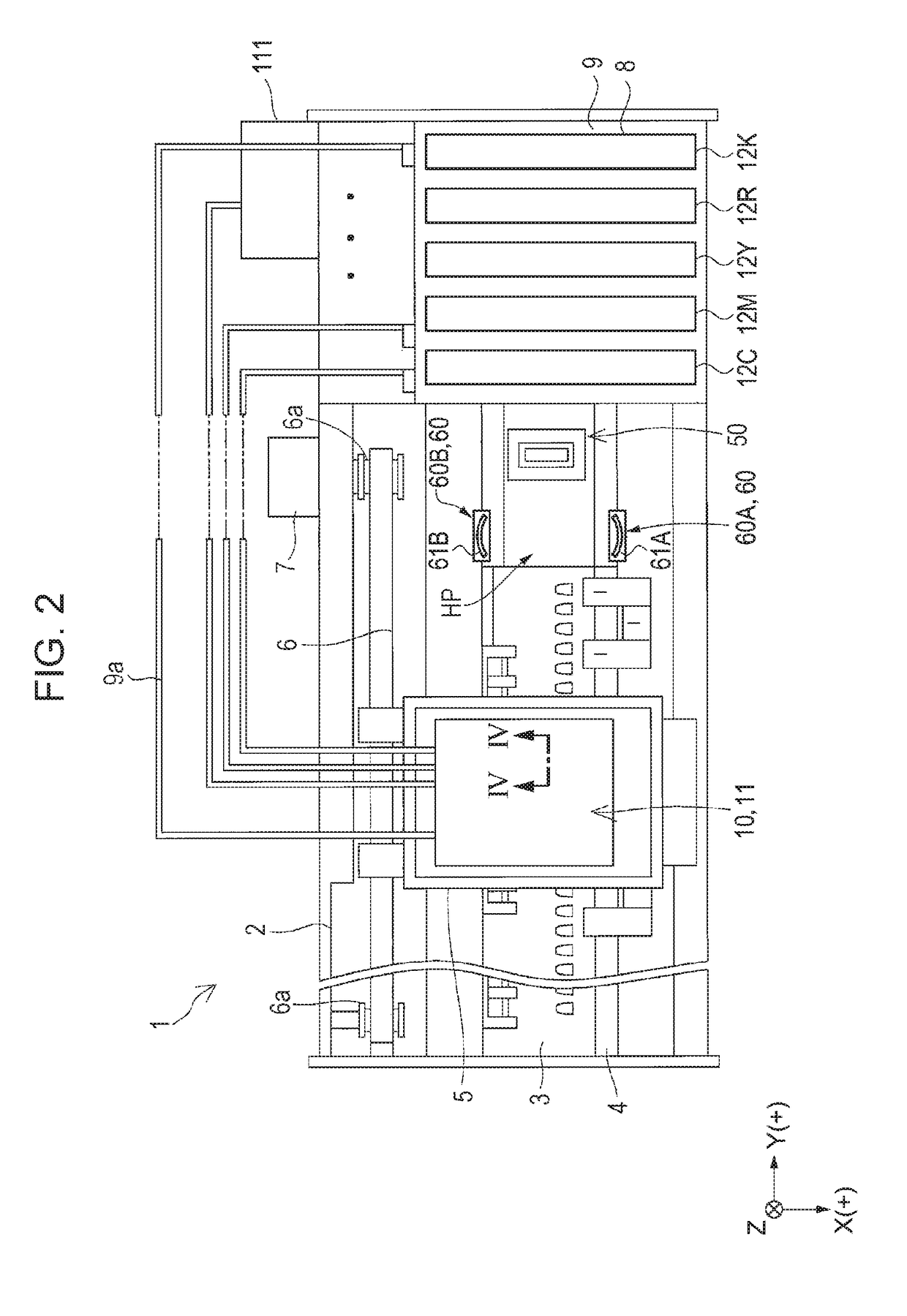
[0064]FIG. 1 is a diagram schematically illustrating a configuration of a printing system 100 according to Embodiment 1. FIG. 2 is a plan view schematically illustrating a state of an ink jet type recording apparatus (hereinafter, referred to as a printer) according to the embodiment.

[0065]First, an overview of a printer 1 according to the embodiment is described with reference to FIGS. 1 and 2.

[0066]As illustrated in FIG. 1, the printing system 100 is configured to include the printer 1 as an example of a “liquid discharge apparatus”, and a computer 101.

[0067]The computer 101 is communicably connected to the printer 1 and outputs print data in response to an image to the printer 1. The printer 1, based on the print data output from the computer 101, ejects (discharges) an ink 12 (refer to FIG. 2) as an example of a “liquid” to a recording medium such as paper or a resin sheet, and records (prints) an image or the like on the recording medium.

[0068]The print...

embodiment 2

[0225]FIG. 10 is a plan view schematically illustrating a state of a printer according to Embodiment 2. FIG. 11 is a view corresponding to FIG. 8, and is a plan view schematically illustrating the state of the wiping process.

[0226]The wiping portion 60 is provided at one position in the printer 1A according to the embodiment. The wiping portion 60 is provided at two positions in the printer 1 according to Embodiment 1. This is a difference between the embodiment and Embodiment 1.

[0227]Hereinafter, the printer 1A according to the embodiment is described by focusing on the differences from the printer 1 according to Embodiment 1, with reference to FIGS. 10 and 11. In addition, the same reference signs are assigned to the same components as those in Embodiment 1, and repeated description thereof is omitted.

[0228]As illustrated in FIG. 10, in the printer 1A according to the embodiment, the wiping portion 60 is provided on the X(+) direction side of the home position region HP. The wipin...

embodiment 3

[0240]FIG. 12 is a view corresponding to FIG. 8, and is a plan view schematically illustrating the state of the wiping process in a printer according to Embodiment 3. FIG. 13 is a schematic sectional view taken along line XIII-XIII in FIG. 12.

[0241]In the printer according to the embodiment, the moving direction of the wiper 61 with respect to the wiping surface 11 is different from that in the printer 1 according to Embodiment 1. In other words, the embodiment differs from Embodiment 1 in that the wiper moves in the Y direction in the embodiment, and the wiper moves in the X direction in Embodiment 1.

[0242]Hereinafter, the wiping process of the printer according to the embodiment is described by focusing on the differences from the printer 1 according to Embodiment 1, with reference to FIGS. 12 and 13. In addition, the same reference signs are assigned to the same components as those in the embodiment 1, and repeated description thereof is omitted.

[0243]As illustrated in FIG. 12, o...


PUM


Abstract

A liquid discharge apparatus includes: a wiper; a wiping surface for wiped with the wiper; a plurality of nozzles provided in the wiping surface; a piezoelectric element for discharging inks from the nozzles; and a carriage unit and a cleaning unit configured to cause the wiper and the wiping surface to relatively move. In a moving direction of the wiper with respect to the wiping surface, a distance between a side of the wiping surface on an upstream side in the moving direction and the nozzle disposed on the most upstream side is shorter than a distance between a side of the wiping surface on a downstream side in the moving direction and the nozzle disposed on the most downstream side.

Description

BACKGROUND[0001]1. Technical Field[0002]The present invention relates to a liquid discharge apparatus and a method for wiping a liquid discharge head mounted in the liquid discharge apparatus.[0003]2. Related Art[0004]As a liquid discharge apparatus that discharges a liquid to a recording medium, an ink jet type recording apparatus that discharges an ink as the liquid and performs printing on the recording medium such as paper or a recording sheet has been known.[0005]Since an ink jet type recording head mounted in such an ink jet type recording apparatus discharges an ink as ink droplets from a nozzle, the ink is attached to the vicinity of the nozzle. Further, when viscosity of the attached ink is increased, there is a problem in that a discharge direction of ink droplets becomes unstable or a problem in that it is difficult to appropriately discharge ink droplets.[0006]Therefore, cleaning by wiping, with a wiper, a nozzle surface, in which the nozzles of the ink jet type recordin...

Claims


Application Information

Patent Timeline
IPC IPC(8): B41J2/165
CPCB41J2/16544B41J2/16541B41J2/16502B41J2/16538B41J2/16585B41J2/16535
Inventor MUTO, ATSUSHI
Owner SEIKO EPSON CORP
Why Eureka
Try Eureka