Liquid ejection head, liquid ejection apparatus, and method of supplying liquid

Active Publication Date: 2017-07-13
CANON KK
View PDF1 Cites 25 Cited by
  • Summary
  • Abstract
  • Description
  • Claims
  • Application Information

AI Technical Summary

Benefits of technology

[0006]An object of the present invention is to provide a liquid ejection head, a liquid ejection apparatus, and a method of supplying liquid capable of suppressing a change in qual

Problems solved by technology

For example, in a liquid ejection head that ejects ink, ink may be thickened or a color material concen

Method used


Image

  • Liquid ejection head, liquid ejection apparatus, and method of supplying liquid
  • Liquid ejection head, liquid ejection apparatus, and method of supplying liquid
  • Liquid ejection head, liquid ejection apparatus, and method of supplying liquid

Examples


first application example

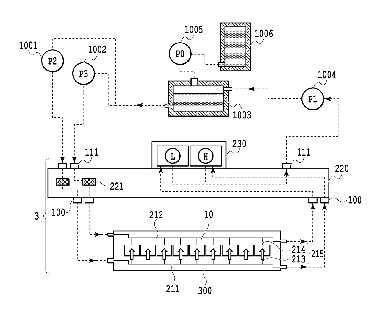
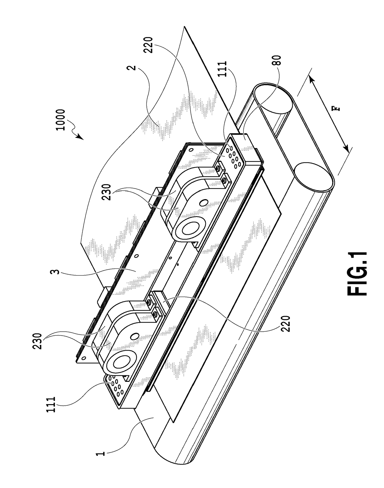
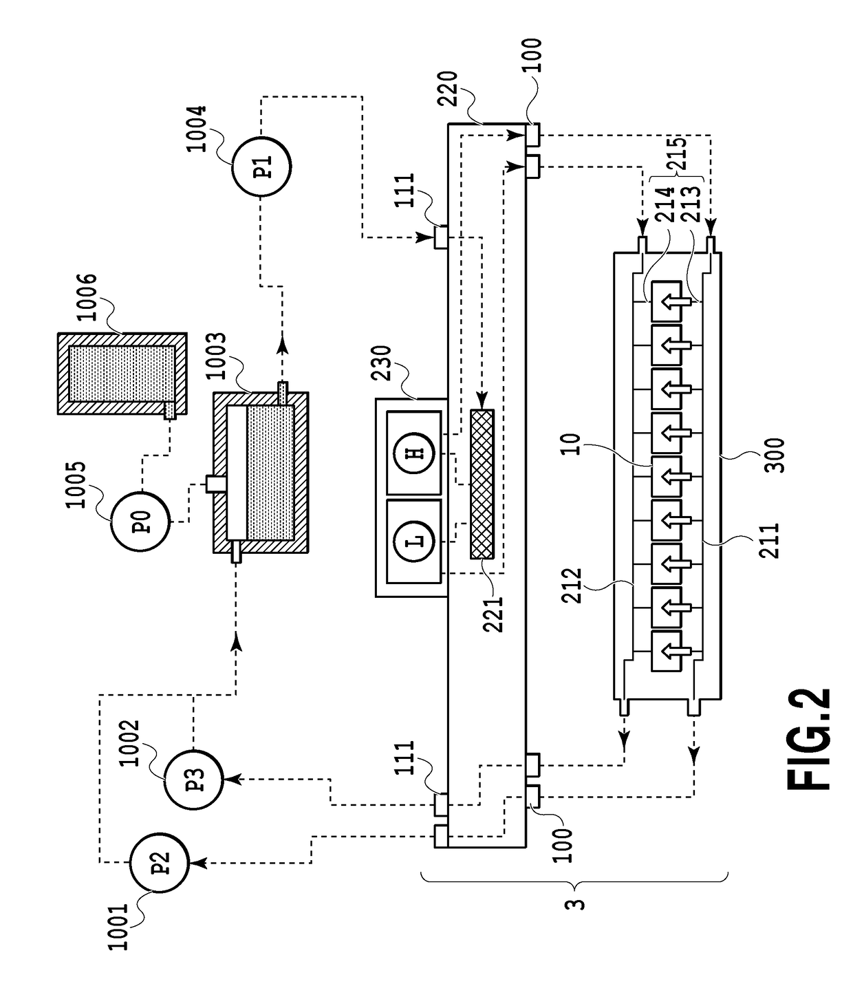
[0071]FIG. 1 is a diagram illustrating a schematic configuration of a liquid ejection apparatus that ejects a liquid in the invention and particularly an inkjet printing apparatus (hereinafter, also referred to as a printing apparatus) 1000 that prints an image by ejecting ink. The printing apparatus 1000 includes a conveying unit 1 which conveys a print medium 2 and a line type (page wide type) liquid ejection head 3 which is disposed to be substantially orthogonal to the conveying direction of the print medium 2. Then, the printing apparatus 1000 is a line type printing apparatus which continuously prints an image at one pass by ejecting ink onto the relative moving print mediums 2 while continuously or intermittently conveying the print mediums 2. The liquid ejection head 3 includes a negative pressure control unit 230 which controls a pressure (a negative pressure) inside a circulation path, a liquid supply unit 220 which communicates with the negative pressure control unit 230 ...

second application example

[0116]Next, configurations of an inkjet printing apparatus 2000 and a liquid ejection head 2003 according to a second application example of the invention, which are different from the above described first application example, will be described with reference to the drawings. In the description below, only a difference from the first application example will be described and a description of the same components as those of the first application example will be omitted.

[0117]FIG. 21 is a diagram illustrating the inkjet printing apparatus 2000 according to the application example used to eject the liquid. The printing apparatus 2000 of the application example is different from the first application example in that a full color image is printed on the print medium by a configuration in which four monochromic liquid ejection heads 2003 respectively corresponding to the inks of cyan C, magenta M, yellow Y, and black K are disposed in parallel. In the first application example, the numbe...

third application example

[0128]Configurations of the inkjet printing apparatus 1000 and the liquid ejection head 3 according to a third application example of the present invention will be described. The liquid ejection head of the third application example is of a page wide type in which an image is printed on a print medium of a B2 size through one scan. Since the third application example is similar to the second application example in many respects, only difference from the second application example will be mainly described in the description below and a description of the same configuration as that of the second application example will be omitted.

[0129]FIG. 51 is a schematic diagram illustrating an inkjet printing apparatus according to the application example. The printing apparatus 1000 has a configuration in which an image is not directly printed on a print medium by the liquid ejected from the liquid ejection head 3. That is, the liquid is first ejected to an intermediate transfer member (an inte...


PUM


Abstract

A liquid ejection head including: an ejection opening; a passage in which an energy generation element is disposed; an ejection opening portion that allows communication between the ejection opening and the passage; a supply passage for allowing the liquid to flow into the passage; and an outflow passage for allowing the liquid to flow out to the outside, wherein an expression of H−0.34×P−0.66×W>1.7 is satisfied when a height of the passage is set to H, a length of the ejection opening portion is set to P, and a length of the ejection opening portion is set to W.

Description

BACKGROUND OF THE INVENTION[0001]Field of the Invention[0002]The present invention relates to a liquid ejection head, a liquid ejection apparatus, and a method of supplying liquid, and specifically relates to a liquid ejection head that performs an ejection operation while allowing liquid to flow through a passage between a liquid ejection opening and an element generating ejection energy.[0003]Description of the Related Art[0004]Japanese Patent Laid-Open No. 2002-355973 describes this type of liquid ejection head that performs ink ejection operation while circulating ink in a passage between an ejection opening and a heating resistor that generates ejection energy, of the liquid ejection head, by causing ink circulation in the liquid ejection head. According to this configuration, it is possible to eject ink which is thickened when moisture, etc. of ink evaporates due to heat generated as a result of the ejection operation, and to supply new ink. As a result, it is possible to prev...

Claims


Application Information

Patent Timeline
IPC IPC(8): B41J2/175B41J2/14
CPCB41J2/1433B41J2/175B41J2/1404B41J2002/14475B41J2202/11B41J2202/12B41J2/14024B41J2/14072B41J2/18B41J2202/20B41J2202/21B41J2002/012B41J2002/14403
Inventor OKUSHIMA, SHINGOKARITA, SEIICHIROAOKI, TAKATSUNANAGAI, NORIYASUNISHITANI, EISUKENAKAGAWA, YOSHIYUKI
Owner CANON KK
Why Eureka
Try Eureka