Unlock instant, AI-driven research and patent intelligence for your innovation.

Touch screen controller

a touch screen controller and touch screen technology, applied in the field of touch screen controllers, can solve the problems of lowering the accuracy of touch control, affecting the recognition of touch control, and the inability of the touch screen controller of a conventional touch screen to transmit a high working voltage signal, so as to achieve the best signal-to-noise ratio and optimal touch control recognition performan

Inactive Publication Date: 2017-07-13
EGALAX EMPIA TECH INC
View PDF2 Cites 2 Cited by
  • Summary
  • Abstract
  • Description
  • Claims
  • Application Information

AI Technical Summary

Benefits of technology

The present invention is a touch screen controller that improves the accuracy and performance of touch control recognition. It includes a driving circuit and a sensing circuit. The driving circuit sends a high voltage signal to the touch screen, which then generates a low voltage signal. The sensing circuit receives this low voltage signal and compares it to the high voltage signal to determine any changes or variations. This allows the controller to recognize a touch on the screen with optimal accuracy. The high voltage signal is five times stronger than the low voltage signal, which ensures the best signal-to-noise ratio and optimal performance in touch control recognition.

Problems solved by technology

When clicking these minimized physical input keys, the user may inadvertently click a wrong key, leading to considerable trouble and inconvenience in input operation.
If the voltage of the touch screen driving signal is low, the controller will be unable to accurately detect the touch on the touch screen, lowering touch control accuracy.
Thus, the touch screen controller of a conventional touch screen cannot transmit a high working voltage signal.
During the operation of a conventional touch screen to couple a high working voltage signal, surrounding noises can get into the signal, lowering the signal-to-noise ratio (SNR) of the signal detected by the touch screen controller and affecting the accuracy of the functioning of the touch screen controller in determining the location of the touch on the touch screen.

Method used


Image

  • Touch screen controller
  • Touch screen controller
  • Touch screen controller

Examples


Embodiment Construction

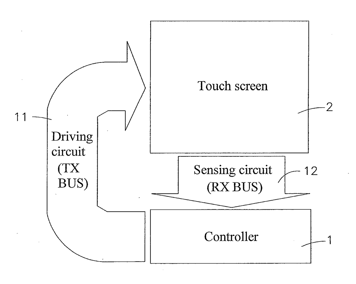
[0025]Referring to FIGS. 1 and 2, a controller 1 for use in a touch screen 2 in accordance with the present invention is shown. The controller 1 comprises a driving circuit (TX) 11 and a sensing circuit (RX) 12.

[0026]The driving circuit 11 of the controller 1 is made using a high-voltage semiconductor manufacturing process. The sensing circuit 12 of the controller 1 is made using a low-voltage semiconductor manufacturing process. The controller 1 uses the driving circuit 11 to provide a high working voltage to the touch screen 2, enabling a high voltage signal to go through the touch screen 2. Thereafter, the controller 1 controls the sensing circuit 12 to receive a detection signal from the touch screen 2, and then performs an algorithm to analyze signal variation for determination of any touch on the touch screen 2.

[0027]The driving circuit 11 of the controller 1 is made through a semiconductor high voltage manufacturing process, such as drain extended metal oxide semiconductor (D...


PUM


Abstract

A touch screen controller includes a driving circuit adapted for transmitting a high working voltage signal to the touch screen for enabling the touch screen to couple the high working voltage signal and to further generate a low working voltage signal, and a sensing circuit adapted for receiving the low working voltage signal from the touch screen for matching with the high working voltage signal to determine the variation in signal voltage between the high working voltage signal and the low working voltage signal and to further recognize a touch on the touch screen. The voltage level of the high working voltage signal provided by the driving circuit is five times over the voltage level of the low working voltage signal so that the sensing circuit can get the best signal-to-noise ratio, achieving optimal performance in touch control recognition.

Description

[0001]This application claims the priority benefit of Taiwan patent application number 105100545, filed on Jan. 8, 2016.BACKGROUND OF THE INVENTION[0002]1. Field of the Invention[0003]The present invention relates to touch control technology and more particularly, to a touch screen controller, which comprises a driving circuit for transmitting a high working voltage signal to the touch screen for coupling, and a sensing circuit for receiving the coupled low working voltage signal from the touch screen for matching with the high working voltage signal to determine the signal voltage variation and to further recognize a touch on the touch screen. The voltage level of the high working voltage signal provided by the driving circuit is five times over the voltage level of the low working voltage signal so that the sensing circuit can get the best signal-to-noise ratio, achieving optimal performance in touch control recognition.[0004]2. Description of the Related Art[0005]With the develop...

Claims


Application Information

Patent Timeline
IPC IPC(8): G06F3/041
CPCG06F3/0416G06F3/04164G06F3/044
Inventor LIN, PO-CHUAN
Owner EGALAX EMPIA TECH INC