
Device having a c-arm and x-ray imager

Active Publication Date: 2017-07-20
SIEMENS HEALTHCARE GMBH
View PDF0 Cites 4 Cited by
  • Summary
  • Abstract
  • Description
  • Claims
  • Application Information

AI Technical Summary

Benefits of technology

The invention is about a device with a C-arm and an x-ray imager that has improved movement. It uses an O arrangement of rollers and direct force application to reduce the space between the x-ray source and detector, and also reduces the time it takes for the C-arm to stop or accelerate. This results in less movement and less variation in the amplitude of the resulting oscillations. Overall, this device provides better quality x-ray images.

Problems solved by technology

This results in a relatively great, undesired displacement of the imaging components that are fastened to the C-arm.
Furthermore, the decay time for the resultant oscillation in braking and accelerating operations is increased by the mutual excitement of the “ears”.

Method used


Image

  • Device having a c-arm and x-ray imager
  • Device having a c-arm and x-ray imager
  • Device having a c-arm and x-ray imager

Examples


Embodiment Construction

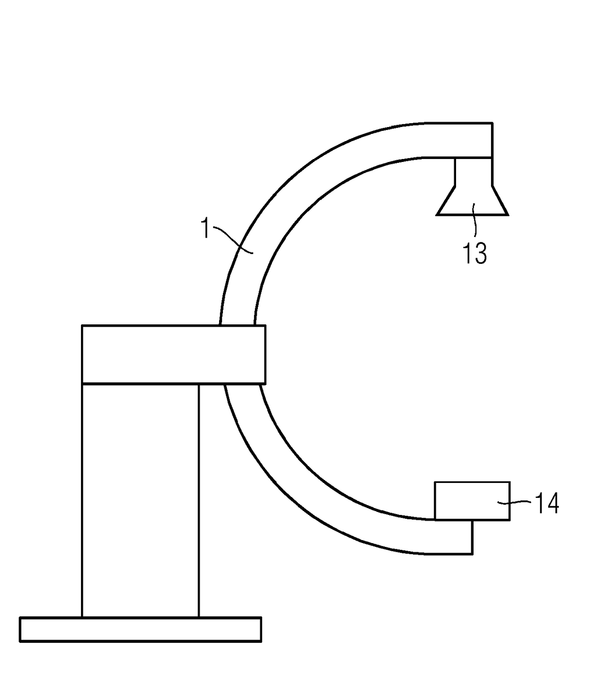
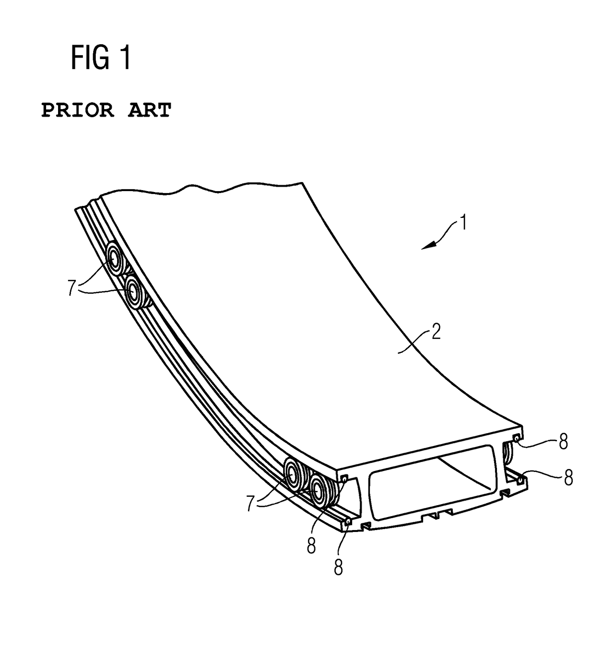
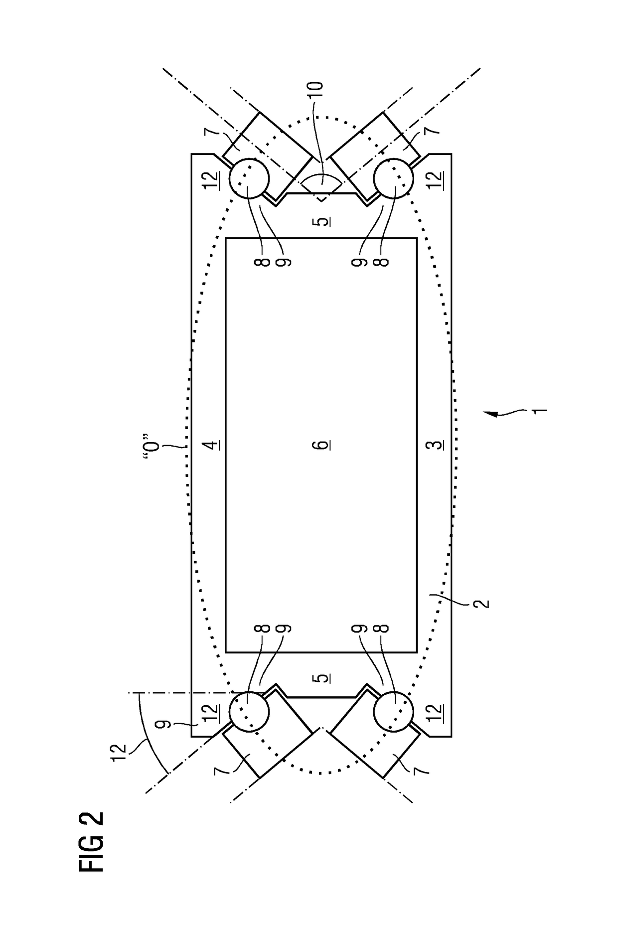
[0023]FIG. 2 depicts a cross section through a C-arm 1, which is movably mounted on running rollers 7. The C-arm 1 includes a main body 2, which in cross-sectional profile, forms a double H. In the core region (e.g., between the outer wall 3, the inner wall 4, and the side walls 5), the main body 2 forms a rectangular cavity 6. The outer wall 3 and the inner wall 4 of the main body 2 are extended beyond the cavity 6 and form legs 12, known as “ears.”

[0024]The legs 12 form with the side walls 5 edges or corners, in which the running wires 8 are arranged. The running rollers 7 roll on the running wires 8. The running wires 8 are set in grooves in the surface of the running wire carriers 9. The surface of the running wire carriers 9 forms with the side walls 5 an angle of inclination 11 of 45 degrees. Since the running rollers 7 are likewise inclined with respect to the side walls 5 by 45 degrees, approximately 50% of the mounting forces that are introduced into the main body due to th...


PUM


Abstract

The disclosure provides a device having a C-arm, the C-arm including a main body of which the cross-sectional profile is formed as a double H, an outer wall, an inner wall and two side walls of the main body forming a rectangular cavity. The device also includes running wires arranged on the main body and running rollers, on which the C-arm is movably mounted, rolling on the running wires. The running wires and the running rollers are arranged in such a way that at least 50 percent of the mounting forces acting on the running wires due to the running rollers is introduced into the side walls of the main body. The disclosure also provides an x-ray imager having such a device. The disclosure offers the advantage that undesired oscillations of the C-arm are avoided.

Description

[0001]The application claims the benefit of German Patent Application No. DE 10 2016 200 442.5, filed Jan. 15, 2016, which is hereby incorporated by reference in its entirety.TECHNICAL FIELD[0002]The disclosure relates to a device having a C-arm, the C-arm including a main body of which the cross-sectional profile is formed as a double H. An outer wall, an inner wall, and two side walls of the main body form a rectangular cavity. Running wires are arranged on the main body and running rollers on which the C-arm is movably mounted may roll on the running wires. The disclosure also provides an x-ray imager having such a device.BACKGROUND[0003]C-arm machines are widely used, for example, in medical technology. In the case of such machines, a diagnostic or treatment device is fastened to a C-shaped main body. Because its shape, the C-arm, and with it the diagnostic or treatment device, may be moved orbitally around a point on a patient that is to be examined or treated. Thus, various an...

Claims


Application Information

Patent Timeline
IPC IPC(8): A61B6/00
CPCA61B6/4441A61B6/00A61B6/40A61B6/44A61B6/4476
Inventor BAUMANN, BERTHOLDGARTNER, RALFKLEBER, MICHAELKLEBER, THOMASKRAMER, ALEXANDERMULZER, HARALDNEUBER, WOLFGANGSCHIRBL, MATTHIASZEIDLER, JOSEF
Owner SIEMENS HEALTHCARE GMBH
Learn More