Bias circuit of electro-absorption modulated laser and calibration method thereof

Active Publication Date: 2012-10-25
ZTE CORP
View PDF1 Cites 12 Cited by
  • Summary
  • Abstract
  • Description
  • Claims
  • Application Information

AI Technical Summary

Benefits of technology

[0006]The disclosure provides a bias circuit of an EML and a calibration method thereof, used for providing a forward bias voltage to the LD in the EML and enable it to generate a bias current, and providing a DC bias voltage to the EAM; the bias circuit and calibration method thereof can reduce power consumption of the EML, optimize the AC coupling, and improve the high-frequency performance of the EML.
[0014]The bias circuit of an EML and the calibration method thereof provided by the disclosure have the following beneficial effects:
[0015]1) because the cathode of the EAM is provided with the positive DC bias voltage, the amplitude of AC signal output by the driver is decreased, and the power consumption of the matching resistor is further reduced;
[0016]2) a ground wire is used to perform AC coupling with the cathode of the EAM, the existing components, such as inductor and magnetic bead, of the DC bias voltage circuit are abandoned, thereby the AC coupling is optimized, and the high-frequency performance of the EML can be improved; and
[0017]3) use of a feedback control circuit improves the quality of optical signal output by the EML, which means the jitter of the output optical signal is small, the margin of eye-diagram is large, and the dispersion cost is small, thereby improving the overall performance of the EML.

Problems solved by technology

However, the driver and the EAM use a DC coupling mode; in order to achieve good indexes of high extinction ratio and dispersion cost, the amplitude of the alternate current signal output by the driver is required to be large enough, so the required power consumption of the driver is high, which causes the high power consumption of the EML.
However, the DC bias voltage circuit (BIAS-T2) in FIG. 2 is set between the driver and the EAM, and the DC bias voltage circuit in the traditional art generally includes components, such as inductor; because the used components are not ideal, the parasitic parameters are unavoidable, namely, there exist parasitic resistance and parasitic capacitance, which causes a high-frequency AC signal output by the driver to be shunted by the BIAS-T2, thereby the high-frequency AC signal to the EAM is lost; the loss causes large jitter of output optical carrier wave of the laser and small margin of eye-diagram module, which decreases high-frequency performance of the laser.

Method used


Image

  • Bias circuit of electro-absorption modulated laser and calibration method thereof
  • Bias circuit of electro-absorption modulated laser and calibration method thereof
  • Bias circuit of electro-absorption modulated laser and calibration method thereof

Examples


Embodiment Construction

[0026]The embodiment of a bias circuit of an EML and a calibration method thereof provided by the disclosure is described below with reference to the accompanying drawings in detail.

[0027]The bias circuit of an EML provided by the disclosure includes:

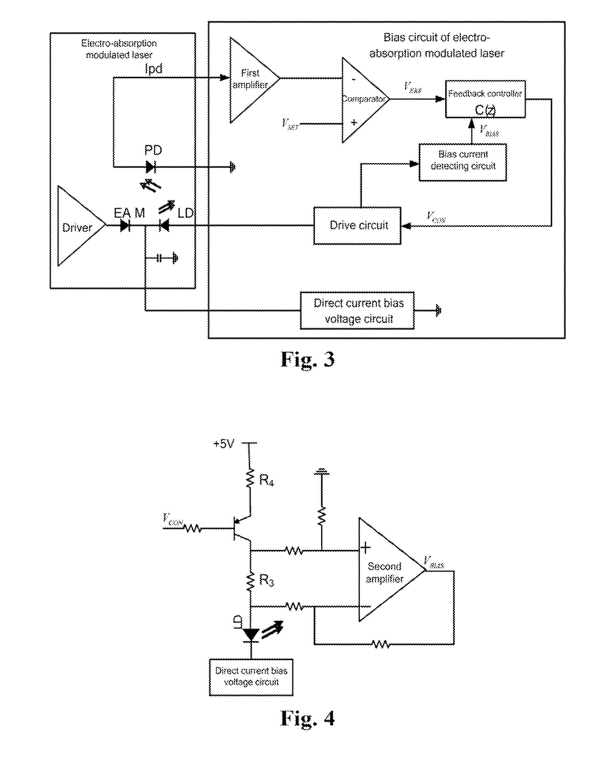
[0028]a drive circuit, which is used for providing an LD in the EML with a forward bias voltage, which enables the LD to generate laser; the LD in the EML is used for generating laser under the drive of the forward bias voltage; as described above, only based on the forward bias voltage, there is bias current existing, and then the LD can generate laser; and

[0029]a direct current bias voltage circuit, which is connected to a cathode of an electro-absorption modulator in the electro-absorption modulated laser, wherein the direct current bias voltage circuit is used for providing a positive direct current bias voltage to the cathode of the electro-absorption modulator and causing a reverse bias voltage of the electro-absorption modulator ...


PUM


Abstract

A bias circuit of an electro-absorption modulated laser and a calibration method thereof are provided. The bias circuit includes a drive circuit and a direct current bias voltage circuit. The drive circuit is used for providing a forward bias voltage to a laser diode in the electro-absorption modulated laser to generate laser. The direct current bias voltage circuit is connected to a cathode of an electro-absorption modulator in the electro-absorption modulated laser, and provides a positive direct current bias voltage to the cathode to enable the reverse bias voltage of the electro-absorption modulator to fall within the range of modulation. When the reverse bias voltage falls within the range of modulation, the electro-absorption modulator utilizes the laser generated by the laser diode as optical carrier wave, modulates the optical carrier wave with the modulation voltage, and outputs a modulated optical signal.

Description

FIELD OF THE INVENTION[0001]The disclosure relates to the technical field of optical fiber transmission, and in particular to a bias circuit coupled to an electro-absorption modulated laser and a calibration method thereof.BACKGROUND OF THE INVENTION[0002]With the development of optical communication, an optical transceiver module is used more and more widely in optical fiber communication systems. The optical transceiver module is a key technology of optical fiber communication systems and plays the role of realizing electrical to optical and optical to electrical conversion, thus its performance has a significant impact on that of optical fiber communication systems. An optical transceiver module usually employs an Electro-absorption Modulated Laser (EML); the EML mainly includes: a Photo-detector (PD), a Laser Diode (LD) and an Electro-absorption Modulator (EAM); the PD is used for converting an optical signal into an electrical signal; the LD is used for generating laser; in ord...

Claims


Application Information

Patent Timeline
IPC IPC(8): H01S3/13H01S3/10
CPCH01S5/0265H01S5/0427H01S5/042H04B10/505H04B10/564
Inventor LV, SHUSHENG
Owner ZTE CORP
Why Eureka
Try Eureka