Tracking Error Signal Calibration Method, and Disc Drive Implementing Such Method

Inactive Publication Date: 2008-04-24
KONINKLIJKE PHILIPS ELECTRONICS NV
View PDF12 Cites 0 Cited by
  • Summary
  • Abstract
  • Description
  • Claims
  • Application Information

AI Technical Summary

Benefits of technology

[0019]In a preferred embodiment, the calibration amplitude is calculated by increasing the calibration amplitude if a new track crossing provides a tracking error signal amplitude larger than the current calibration amplitude, and by decreasing the calibration amplitude if a new track crossi

Problems solved by technology

In practice, however, this is not the case: for several reasons, the relationship between tracking error and tracking error signal may vary over the surface of a storage disc.
However, a disadvantage of this known process of dividing the disc into a plurality of zones and performing calibration procedures (tracking error signal amplitude measurements) in each of those zones, during the start-up phase of the disc, is that it is rather time consuming: each measurement may take about 200 ms, and the number of zones may be in the order of about 10.
This adds to the time a us

Method used


Image

  • Tracking Error Signal Calibration Method, and Disc Drive Implementing Such Method
  • Tracking Error Signal Calibration Method, and Disc Drive Implementing Such Method
  • Tracking Error Signal Calibration Method, and Disc Drive Implementing Such Method

Examples


Embodiment Construction

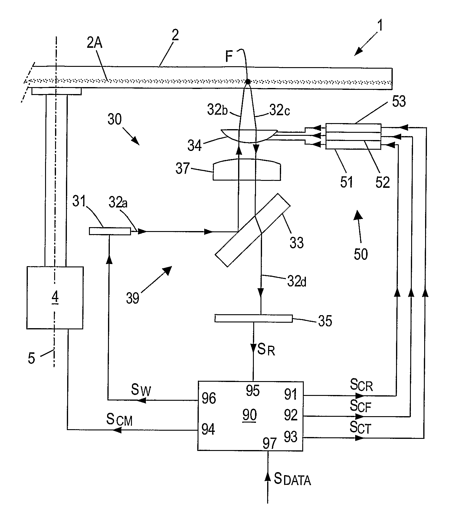
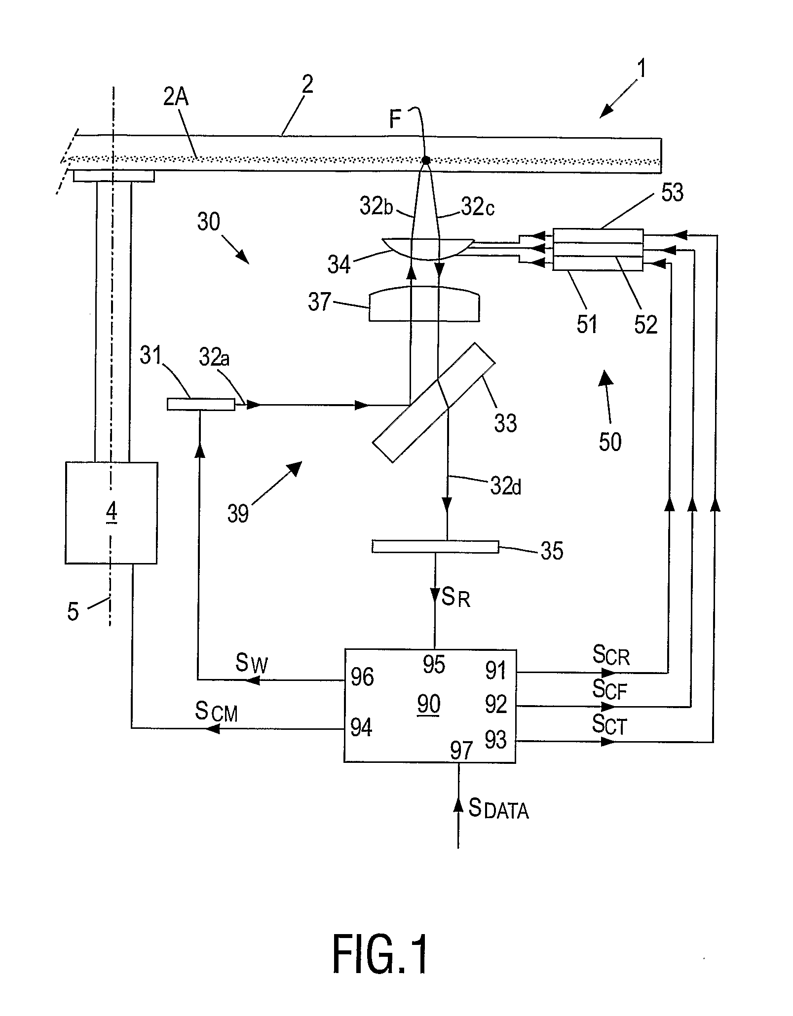
[0030]FIG. 1 schematically illustrates an optical disc drive apparatus 1, suitable for storing information on and reading information from an optical disc 2, typically a DVD or a CD. The disc 2, of which the thickness is shown in an exaggerated way, has at least one storage layer 2A. For rotating the disc 2, the disc drive apparatus 1 comprises a motor 4 fixed to a frame (not shown for the sake of simplicity), defining a rotation axis 5.

[0031]The disc drive apparatus 1 further comprises an optical system 30 for scanning tracks (not shown) of the disc 2 by an optical beam. More specifically, in the exemplary arrangement illustrated in FIG. 1, the optical system 30 comprises a light beam generating means 31, typically a laser such as a laser diode, arranged to generate a light beam 32. In the following, different sections of the light beam 32, following an optical path 39, will be indicated by a character a, b, c, etc. added to the reference numeral 32.

[0032]The light beam 32 passes a...


PUM


Abstract

A method for generating a calibration value (TESC) for a tracking error signal (TES) in an optical disc drive (1) comprises the steps of performing a jump towards a target track of an optical disc (2) inserted in said optical disc drive (1); during at least a part of the jump, calculating the calibration value (TESC) as an approximation of the average of a plurality of tracking error signal amplitudes (TESA(i)) corresponding to a plurality of track crossings.

Description

FIELD OF THE INVENTION[0001]The present invention relates in general to a disc drive apparatus for writing / reading information into / from an optical storage disc; hereinafter, such disc drive apparatus will also be indicated as “optical disc drive”.[0002]More particularly, the present invention relates to e method for calibration and normalization of the tracking error signal.BACKGROUND OF THE INVENTION[0003]As is commonly known, an optical storage disc comprises at least one track, either in the form of a continuous spiral or in the form of multiple concentric circles, of storage space where information may be stored in the form of a data pattern. Optical discs may be read-only type, where information is recorded during manufacturing, which information can only be read by a user. An optical storage disc may also be a writable type, where information may be stored by a user. For writing information in the storage space of the optical storage disc, or for reading information from the ...

Claims


Application Information

Patent Timeline
IPC IPC(8): G11B7/09G11B7/125G11B20/18
CPCG11B7/08517G11B7/0948G11B7/0945G11B7/094G11B7/09
Inventor VAN DER HEIJDEN, HENDRIKUS C.M.
Owner KONINKLIJKE PHILIPS ELECTRONICS NV
Why Eureka
Try Eureka