
Monolithically configured spectroscopic instrument

Active Publication Date: 2019-12-05
FRAUNHOFER GESELLSCHAFT ZUR FOERDERUNG DER ANGEWANDTEN FORSCHUNG EV
View PDF0 Cites 4 Cited by
  • Summary
  • Abstract
  • Description
  • Claims
  • Application Information

AI Technical Summary

Benefits of technology

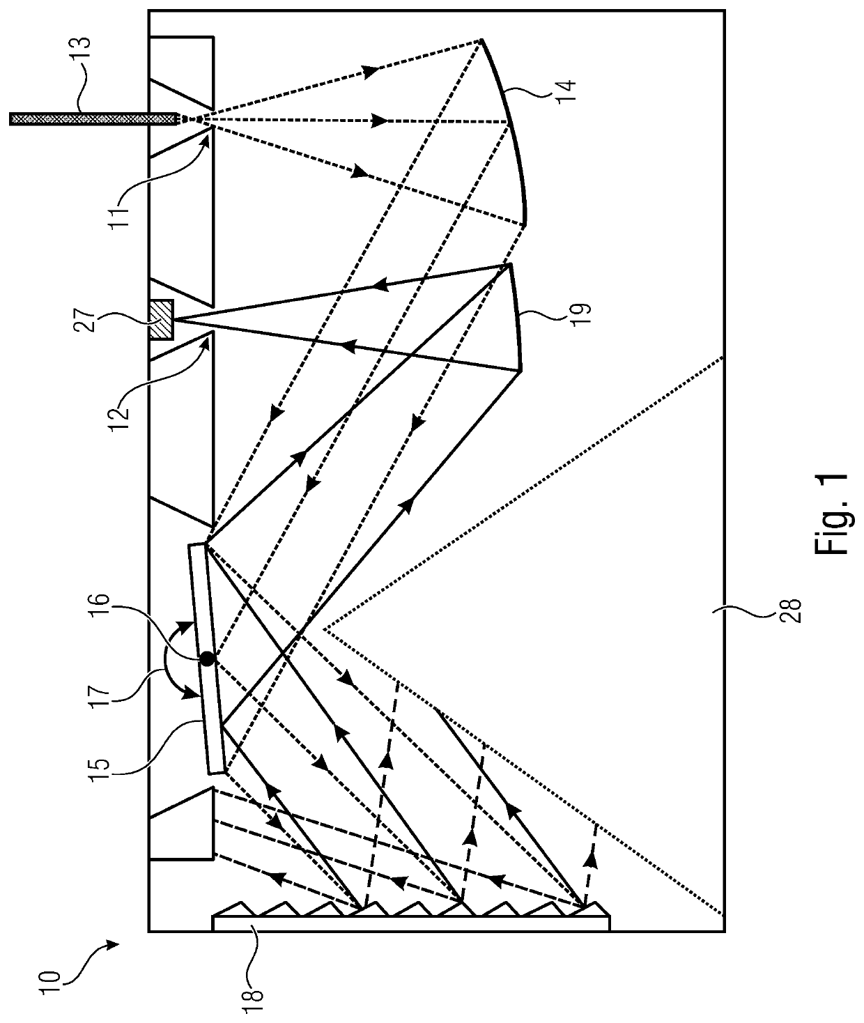
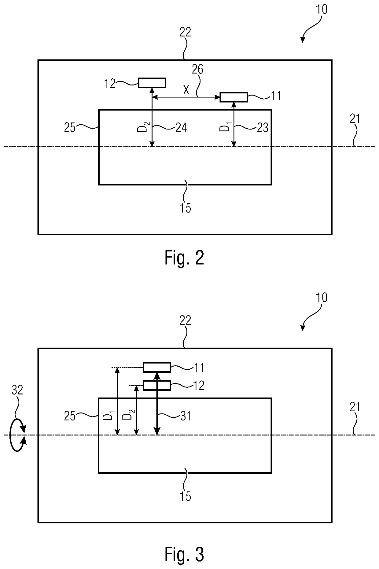
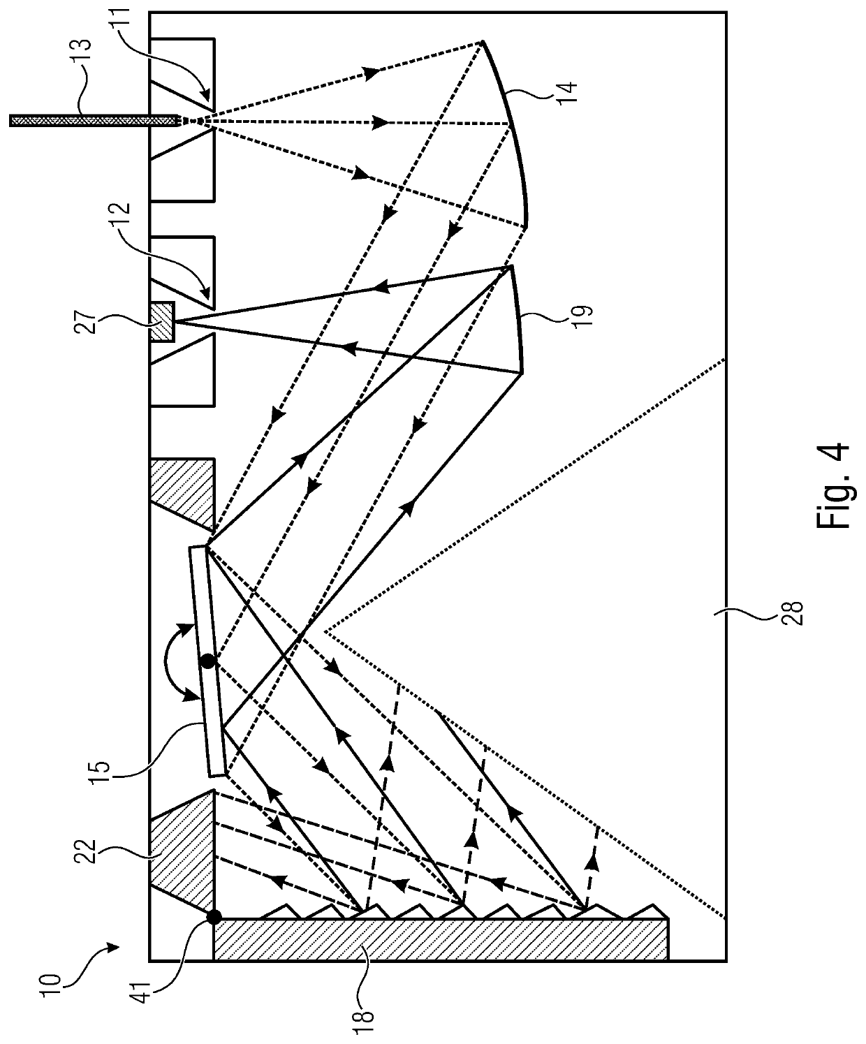
The invention is about a new spectroscopic instrument that uses a MEMS mirror with two apertures and a dispersive element. This arrangement allows for a smaller deflection range of the mirror, which means it only needs to be deflected half as much as a conventional mirror to achieve the same wavelength selection. The monolithic configuration of the components eliminates the need for separate adjustments, resulting in higher accuracy and smaller components. This allows for further miniaturization of the instrument compared to conventional technology.

Problems solved by technology

However, prism spectrographs are disadvantageous because of the inevitable absorption by the material, which is usually non-ideal, of the prism.
The installation size is limited by the size of the detector.
Specifically for array arrangements, these are very costly and comparatively large.
Typical element widths amount to at least 25 μm, but typically 50 μm or more, since the signal noise otherwise becomes problematic.
This results in a width of at least 6 mm for the detector and, therefore, in addition to the high cost, also in a limited miniaturization potential.
In addition, the optical setup may provide a correspondingly wide image field, which involves additional expenditure.
Miniaturization is essentially limited by the useful adjustment of the components.
However, utilization of the folded optical path also entails a problem.
They are complex to manufacture, and with the technologies currently available, production in large numbers is possible only to a limited extent and / or not at sufficiently low cost.
The miniaturization potential is limited by the DLP design size, and the costs of the DLP are comparatively low as compared to current near-infrared spectrometers but are a limiting factor for utilization in mobile phones, as is its size.
The system approaches disclosed in conventional technology impose limits in this respect.
Miniaturization is limited, in particular, by the useful adjustment of the individual components.
The slit diaphragms are arranged along the tilting, or torsional, axis of the torsion element, which renders production of the torsion element more difficult and, therefore, more expensive, however.

Method used


Image

  • Monolithically configured spectroscopic instrument
  • Monolithically configured spectroscopic instrument
  • Monolithically configured spectroscopic instrument

Examples


Embodiment Construction

[0046]In the following, embodiments will be described in more detail with reference to the figures, elements having identical or similar functions being provided with identical reference numerals.

[0047]In addition, optical radiation shall be mentioned herein by way of example of electromagnetic radiation in general. Depending on the implementation of the inventive spectroscopic instrument, the optical radiation may be light of different wavelength ranges. For example, it may be infrared light, e.g., within the near-infrared range. However, in the inventive spectroscopic instrument it is also possible to use optical radiation within other wavelength ranges, e.g., within wavelength ranges which may range from ultraviolet (UV) to infrared (IR) via visible light (VIS).

[0048]In addition, slit diaphragms shall be mentioned as an example of aperture-limiting devices. Further conceivable examples of aperture limiting devices may be, for example, small openings, so-called pinholes, the ends ...


PUM


Abstract

A spectroscopic instrument includes a first aperture limiting device, a second aperture limiting device, a first mirror, a movable MEMS mirror, and a dispersive element spatially separate from the MEMS mirror, the movable MEMS mirror being movable in relation to the dispersive element, the movable MEMS mirror being monolithically configured as a common component with at least one of the first aperture limiting device, the second aperture limiting device, and the dispersive element, and the first and second aperture limiting devices being arranged to be spatially separate from the movable MEMS mirror and having a lateral offset from a rotational axis of the movable MEMS mirror.

Description

CROSS-REFERENCE TO RELATED APPLICATION[0001]This application claims priority from German Patent Application No. DE 10 2018 208 684.2, which was filed on Jun. 1, 2018, and is incorporated herein in its entirety by reference.[0002]The invention relates to a spectroscopic instrument comprising a MEMS mirror, which is monolithically configured as a common component with at least one aperture limiting device or a dispersive element. In particular, the spectroscopic instrument is a miniaturized spectroscopic instrument comprising a wide spectral range which may be employed for spectral analyses of different kinds.BACKGROUND OF THE INVENTION[0003]The method of spectral analysis has been known and become established for laboratory use for a long time. Various approaches are possible. Samples which themselves emit radiation within an addressable range may be analyzed directly, so-called “emission spectroscopy”.[0004]If the sample emits no radiation, or if the intensity of the spectral range ...

Claims


Application Information

Patent Timeline
IPC IPC(8): G01J3/26G01J3/18G01J3/14G01J3/06
CPCG01J3/06G01J3/14G01J3/26G01J2003/1295G01J3/18G01J3/0259G01J3/021G01J3/0275G01J3/0229G01J3/0291G01J2003/064
Inventor GRUEGER, HEINRICHKNOBBE, JENSPUEGNER, TINO
Owner FRAUNHOFER GESELLSCHAFT ZUR FOERDERUNG DER ANGEWANDTEN FORSCHUNG EV
Learn More