
Method and device for controlling the initial opening of a thermostat regulating the temperature of an internal combustion engine

Inactive Publication Date: 2012-06-19
RENAULT SA
View PDF15 Cites 3 Cited by
  • Summary
  • Abstract
  • Description
  • Claims
  • Application Information

AI Technical Summary

Benefits of technology

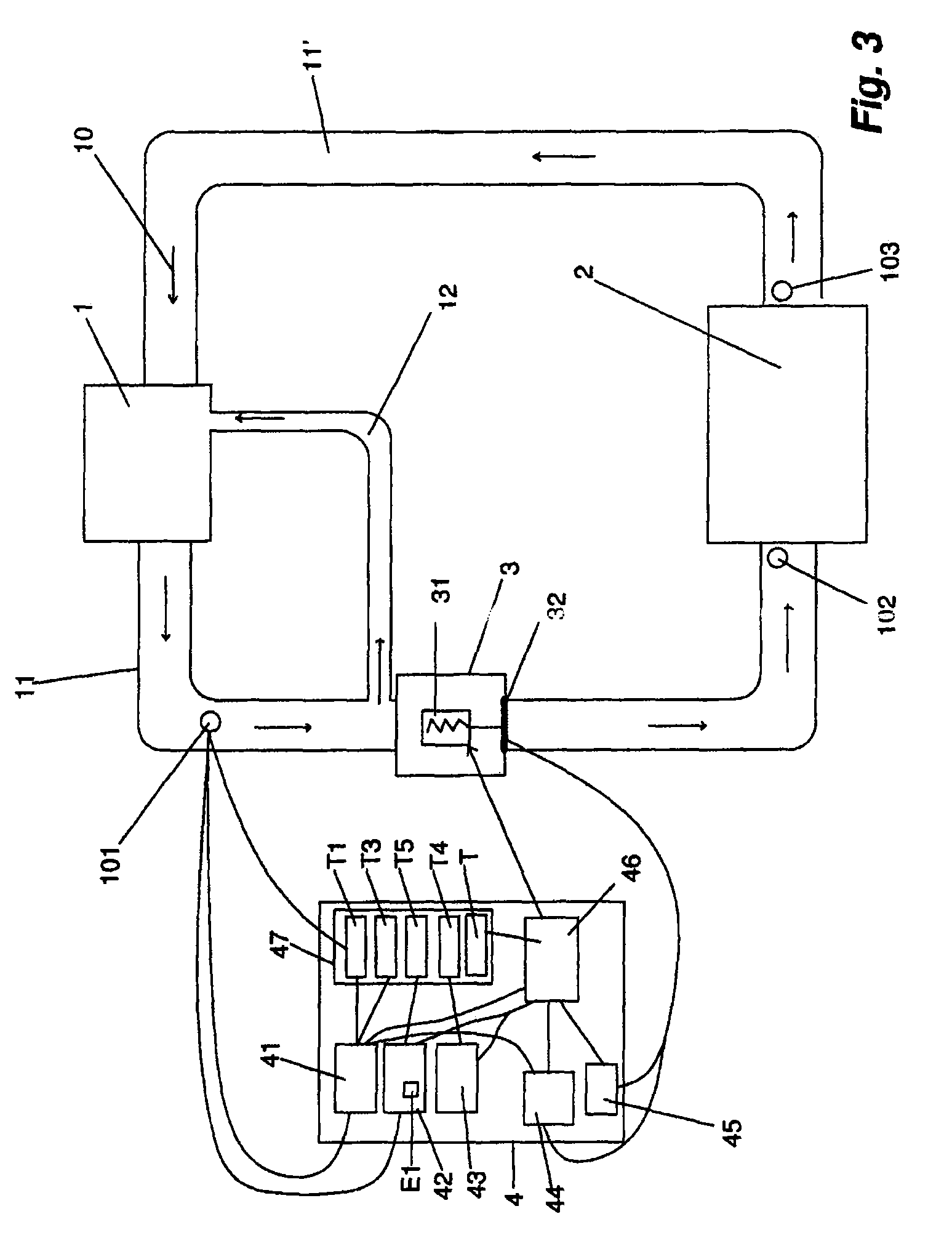
[0019]It is therefore the object of the present invention to reduce the drawbacks by a device whereof the control adapted to the valve control system (a thermostat here) serves to reduce the amplitude of the thermal shock on the components by performing a control according to a criterion selected with regard to the coolant temperature and by monitoring the effective opening of the valve control system, also with regard to the temperature.

Problems solved by technology

In fact, at low temperature, the lubricating oil of the internal combustion engine has a high viscosity, which causes additional friction in the engine and consequently extra fuel consumption.
Thus by increasing the temperature of the engine cooling water, the oil temperature is thereby increased and the friction losses are reduced, whereas a lower temperature will limit the production of nitrogen oxide in particular.
Yet a problem arises particularly during the first starting of the vehicle.
This thermal shock has negative effects on the auxiliary components surrounding the engine and, in particular, the cooling systems for the engine itself and other cooling systems (passenger compartment unit heater, EGR heat exchangers, water / oil heat exchangers, air conditioning radiator and its condenser, turbocharging air, BVA radiator, etc.) which are vulnerable to changes or passages from one temperature to another engine operating temperature setpoint, generating additional stresses thereon.
These additional stresses cause deformations of the auxiliary components of the engine generated by temperature variations and result in additional mechanical forces.
However, one drawback of the device is that it only acts when the temperature of the engine is higher than an ideal operating temperature, which is about 90° C.
It does not help to avoid the thermal shock.

Method used


Image

  • Method and device for controlling the initial opening of a thermostat regulating the temperature of an internal combustion engine
  • Method and device for controlling the initial opening of a thermostat regulating the temperature of an internal combustion engine
  • Method and device for controlling the initial opening of a thermostat regulating the temperature of an internal combustion engine

Examples


Embodiment Construction

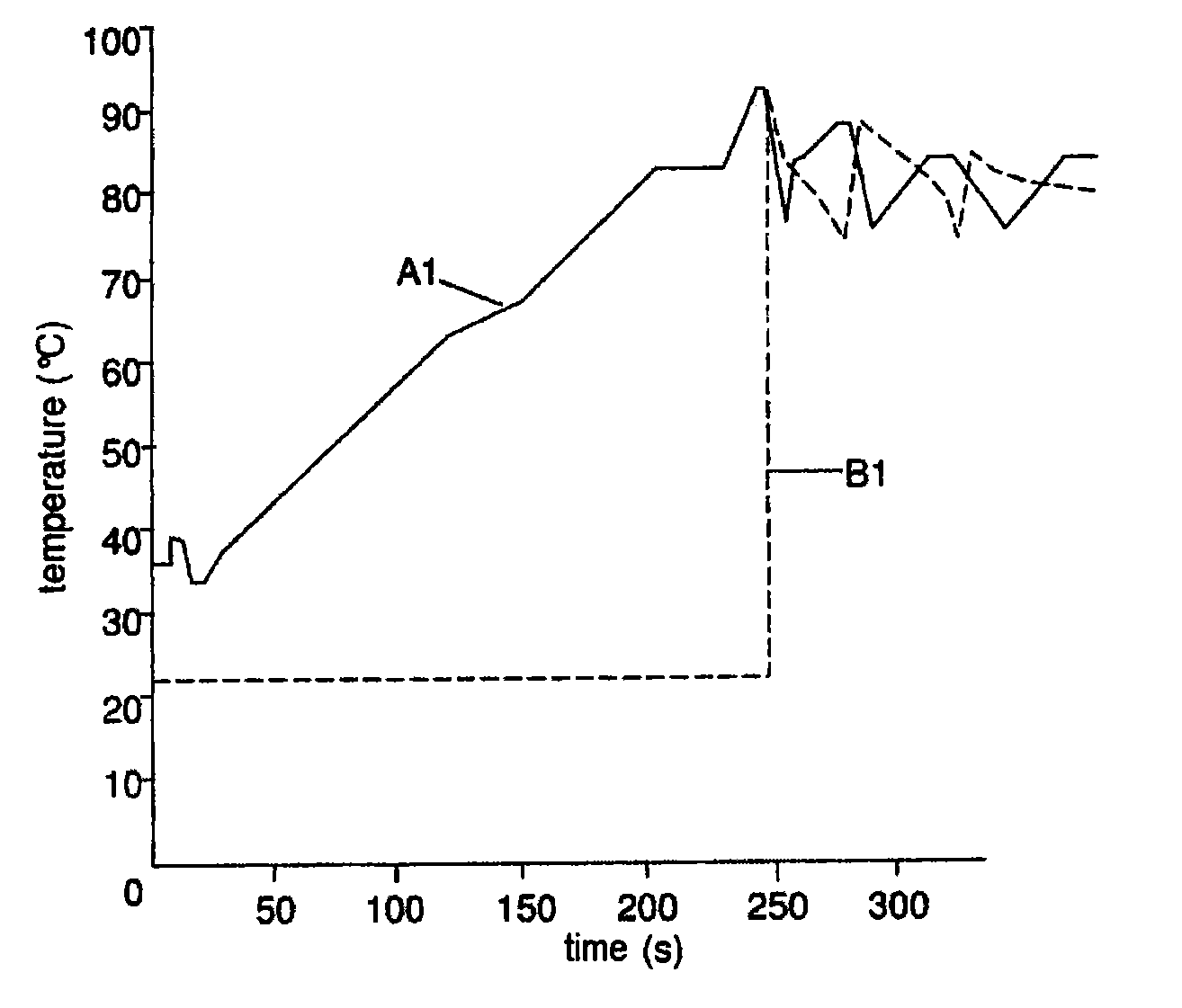
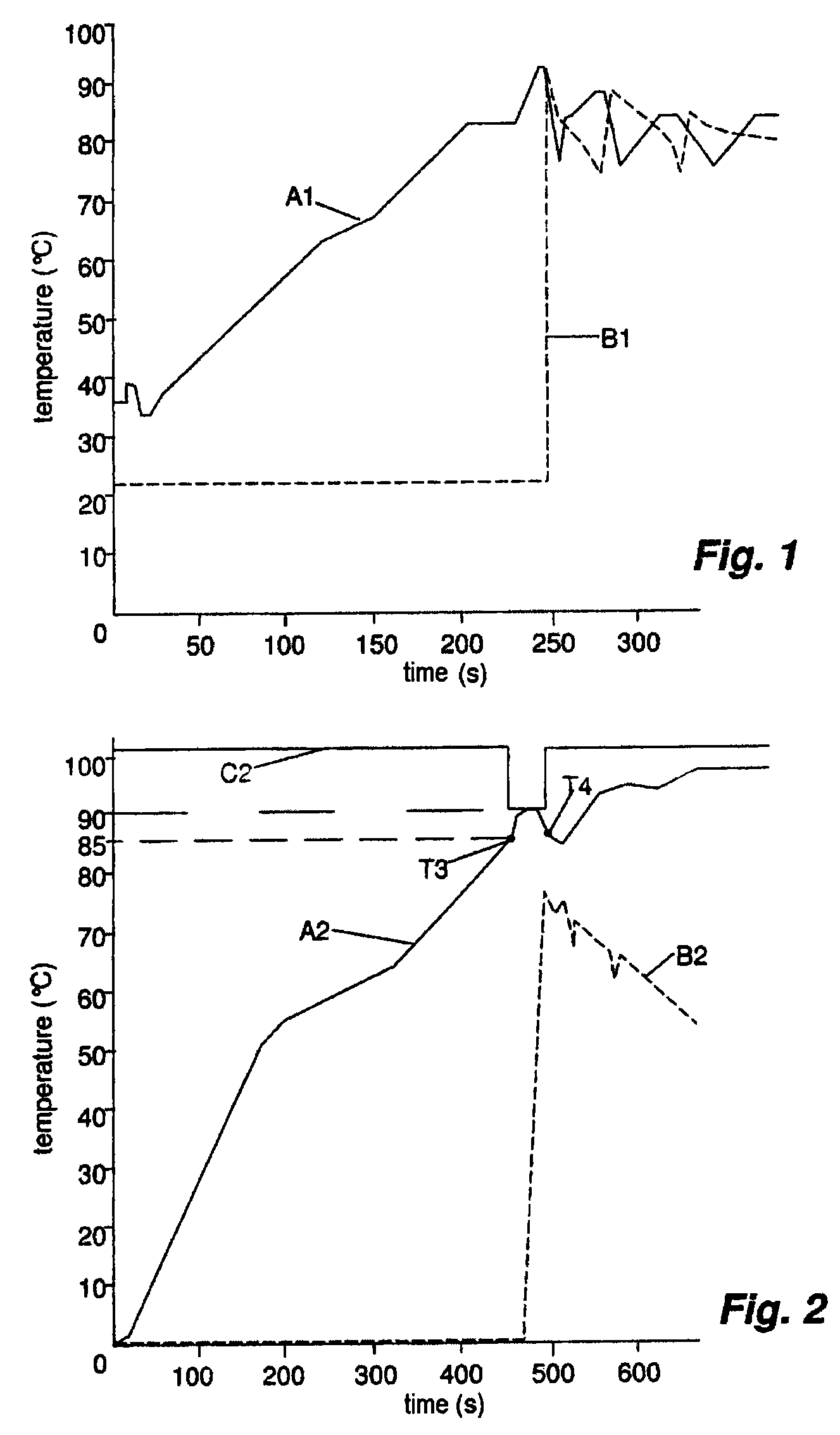
[0045]FIG. 1 shows a first opening of the conventional valve control system, that is uncontrolled. In this type of opening, the device for opening the valve control system comprises a conventional thermostat, as shown previously, of which the expansible liquid serves to open a check valve at a given temperature. In the graph in FIG. 1, the curve A1 represents the coolant temperature, as a function of time, corresponding to the temperature rise of the engine from the time of starting. In the example presented here, the thermostat is set at 90° C. Upon starting, the temperature rises, ordering the opening of the valve control system. This opening allows a passage of the coolant into the heat exchange system, for example a radiator, of which the temperature then increases sharply (shown by the curve B1), while the temperature measured at the engine outlet drops. A very high thermal shock is thus observed (here in the figure, passage from 22° C. to 92° C. or more depending on the engine...


PUM


Abstract

A device for controlling opening of a cooling circuit control valve system of an internal combustion engine, containing a coolant, which is automatically opened under effect of a cooling liquid being heated to a standard temperature. The control performs an early controlled opening of the control valve system of a cooling circuit located upstream of a heat exchanger before the temperature of the cooling liquid reaches a set temperature value for activating the opening of the control valve system, which is itself lower than the standard temperature, the controlled opening being performed only when the control valve system is first opened.

Description

BACKGROUND[0001]The present invention relates to the field of engine control, and more particularly to a method and a device for controlling the first opening of an electronic thermostat regulating the temperature of an internal combustion engine, particularly of a vehicle.[0002]Engine control is the technique of managing an internal combustion engine with all its sensors, actuators and inter-system links (ISL). All the monitoring and control laws (the software strategies) and characterization parameters (calibrations) of an engine are contained in a computer called an electronic control unit (ECU).[0003]Internal combustion engines (with a carburetor or with fuel injection), require cooling that is generally obtained by circulating water or air. This is because an internal combustion engine generates heat. This heat is due to the combustion of the gases and to the various frictions of the moving parts.[0004]In order to confine the expansion between permissible temperature ranges and...

Claims


Application Information

Patent Timeline
IPC IPC(8): F01P7/14
CPCF01P7/167G05D23/30F01P2025/32F01P2037/02F01P2070/04
Inventor MOUNETOU, CHRISTOPHEPINTEAU, FRANCKPREMIER, EMMANUELBOUTONNET, FRANCISAFONSO, VASCOBREUILLE-MARTIN, FRANCK
Owner RENAULT SA
Learn More