Motor rotor and a motor having the same

Inactive Publication Date: 2011-12-22
FAIRCHILD SEMICON CORP
View PDF9 Cites 3 Cited by
  • Summary
  • Abstract
  • Description
  • Claims
  • Application Information

AI Technical Summary

Benefits of technology

[0015]From the above, it can be seen that the irregular arrangement of the first and second magnetic bodies on the inner lateral surface of the annular body prevents a rotating motor from generating a cogging effect, disperses the frequency of cogging torque, reduces the amplitude, and reduces noise generated wh

Problems solved by technology

However, the equal interval arrangement of the permanent magnets results in a cogging effect and cogging torque while a motor is rotating.
If the frequency of the cogging torque is cl

Method used


Image

  • Motor rotor and a motor having the same
  • Motor rotor and a motor having the same
  • Motor rotor and a motor having the same

Examples


Embodiment Construction

[0022]The following illustrative embodiments are provided to illustrate the disclosure of the present invention and advantages thereof. These and other advantages and effects can be readily understood by those in the art after reading the disclosure of this specification. The present invention can also be performed or applied by other embodiments. The details of the specification apply to a specific application; however, numerous modifications and variations can be devised without departing from the spirit of the present invention.

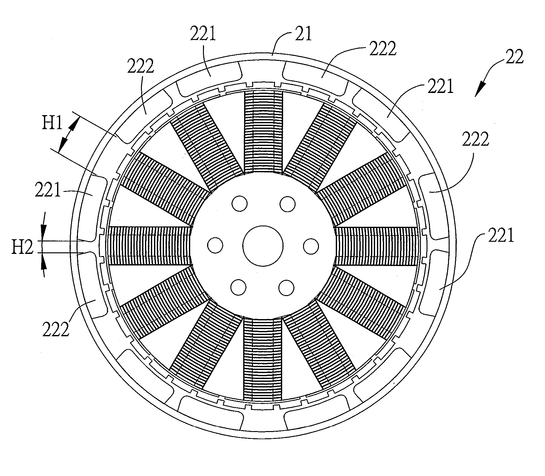
[0023]FIG. 2A is a top view of a motor rotor and its corresponding stator according to the present invention. Referring to FIG. 2A, in the embodiment, the motor rotor of the present invention rotates in cooperation with a stator of a field coil. The field coil generates a magnetic field that drives the motor rotor to rotate.

[0024]As shown in FIG. 2A, the motor rotor comprises an annular body 21 and a magnetic body set 22. The annular body 21 has an inner l...


PUM


Abstract

A motor rotor includes an annular body and a plurality of magnetic bodies installed on an inner lateral surface of the annular body in an irregular manner, to prevent a rotating motor from generating a cogging effect, disperse the frequency of the cogging torque, and reduce the amplitude. Accordingly, noises generated while the motor is operating are reduced, the periodicity of a cogging torque is changed, and cogging torque is reduced.

Description

BACKGROUND OF THE INVENTION[0001]1. Field of the Invention[0002]This invention relates to motor rotors, and, more particularly, to a motor rotor that reduces noises generated by a cogging torque and a motor having the motor rotor.[0003]2. Description of Related Art[0004]Electrical motors are applied to numerous kinds of products. In general, a motor forms an inductive magnetic field by using electrical current. The inductive magnetic field interacts with an inner permanent magnet to generate rotational movement. In addition to providing the rotational movement, the motor may also output rotational mechanical energy that may be converted into a linear or vibrating movement by certain mechanisms.[0005]FIG. 1A (PRIOR ART) provides an oblique view of an outer rotor motor according to the prior art. Referring to FIG. 1A (PRIOR ART), the outer rotor motor comprises a stator 11 installed in the central region and a rotor 12 surrounding the outer circumference of the stator 11. The stator 1...

Claims


Application Information

Patent Timeline
IPC IPC(8): H02K1/27
CPCH02K29/03H02K1/2786H02K1/2791
Inventor YANG, SHIH-JENTU, HUNG-SENYANG, CHEN-CHIA
Owner FAIRCHILD SEMICON CORP
Why Eureka
Try Eureka