
Cash register system with pivotable arms

a cash register and pivoting technology, applied in the field of cash register systems, can solve the problems of high effort and corresponding skill, compact structure, and large space requirements of the cash register system, and achieve the effects of convenient portability, improved adjustment of the arms, and improved access to the receiving area

Active Publication Date: 2017-07-20
DIEBOLD NIXDORF SYST GMBH
View PDF0 Cites 6 Cited by
  • Summary
  • Abstract
  • Description
  • Claims
  • Application Information

AI Technical Summary

Benefits of technology

The cash register system is designed in a compact way, with a small base surface required for usage. The display unit can be easily moved for maintenance without removing the cover of the computer. The system is ready for use again after maintenance. The carrier unit has a space for a computer, which is protected from external impacts. The overall structure of the cash register system allows for easy access to the units while keeping the space requirement compact.

Problems solved by technology

In known cash register systems, due to the displays the receipt printer can only be accessed in a limited manner so that the maintenance is only possible with high effort and corresponding skill.
As a result, the cash register system requires very much space, which is disadvantageous in the case of the usually confined space conditions at supermarket checkout counters.
This results in a particularly compact structure.

Method used


Image

  • Cash register system with pivotable arms
  • Cash register system with pivotable arms
  • Cash register system with pivotable arms

Examples


first embodiment

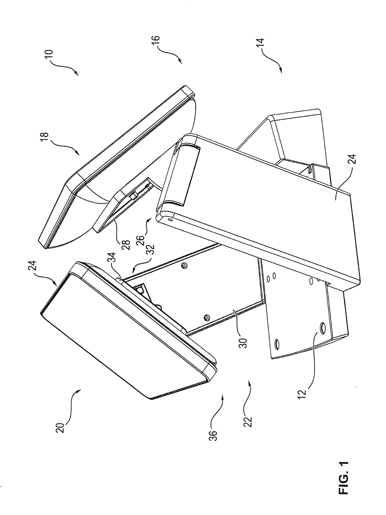
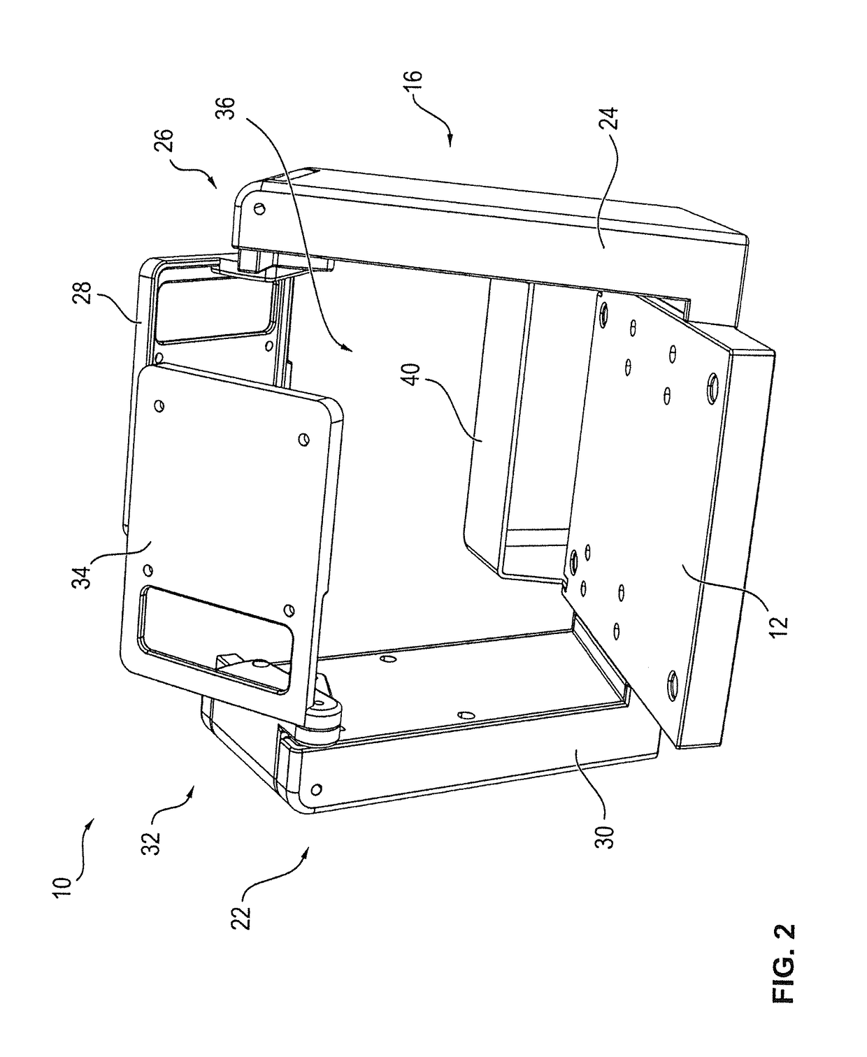
[0044]In FIGS. 1 and 2, a schematic, perspective illustration of a cash register system 10 is illustrated, wherein in FIG. 2 the display units 18, 24 are not illustrated for a better visibility of the other component parts.

[0045]The cash register system 10 comprises a carrier unit 12 via which the cash register system 10 can be placed on a base surface and in particular can also be mounted on this base surface. For mounting purposes, holes through which screws or similar elements can be passed are provided in the plate-shaped carrier unit 12 at least on the underside so that a firm mounting on the base surface is possible. On the upper side of the carrier unit 12, mounting units are preferably likewise provided, via which for example a receipt printer can be mounted on the carrier unit 12.

[0046]Further, on a first side 14, the cash register system 10 has a first arm 16 on which the first display unit 18 is mounted. On a second side 20 opposite to the first side 14, a second arm 22 ...

second embodiment

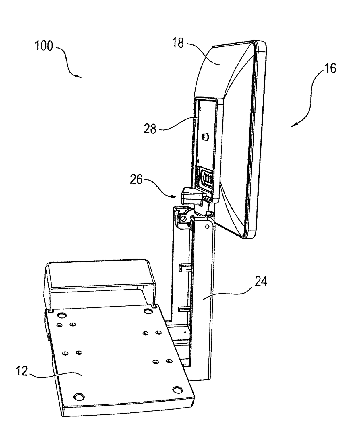
[0062]In FIGS. 7 and 8, in each case a schematic, perspective illustration of a cash register system 100 is shown. Elements having the same structure or the same function are identified with the same reference signs.

[0063]In this second embodiment, the cash register system 100 only has one arm 16. Here, too, a pivoting of the second section 28 and the display unit 18 arranged thereon from the first position shown in FIG. 7 to the second position shown in FIG. 8 can be performed so that a better access to the units receivable in the receiving area 36 is possible.


PUM


Abstract

A cash register system (10, 100) has an arm (16, 22) for holding a display unit (18, 24). The arm (16) has a first section (24, 30) and a second section (28, 34) pivotable relative thereto. The second section (28, 34) is pivotable relative to the first section (28) between a first position in which the display unit (18, 24) is arranged above a receiving area (36) and a second position in which the display unit (18, 24) is not arranged above this receiving area (36).

Description

BACKGROUND[0001]1. Field of the Invention[0002]The invention relates to a cash register system comprising a carrier unit for mounting the cash register system on a base surface, a first display for displaying information to an operator and / or a customer as well as a first arm for holding the display unit.[0003]2. Description of the Related Art[0004]Known cash register systems usually have two display units, one of them being directed to the customer and the other being directed to the cashier. Further, known cash register systems have a computer as well as a receipt printer by means of which the receipt for the customer is printed after the check-out operation. The display units are usually arranged on support arms and directed to the side of the customer and the cashier, respectively.[0005]The receipt printer has to be maintained on a regular basis. In particular, the corresponding paper roll has to be replaced regularly. In known cash register systems, due to the displays the rece...

Claims


Application Information

Patent Timeline
Patent Type & Authority Applications(United States)
IPC IPC(8): G07G1/00
CPCG07G1/0018F16M11/10F16M11/2028F16M11/22F16M2200/024F16M2200/08
Inventor BAITZ, GUENTERLUEKE, WILFRIED
Owner DIEBOLD NIXDORF SYST GMBH
Learn More