
Axle suspension system for a tractor

a technology for axles and agricultural vehicles, applied in resilient suspensions, vehicle springs, vehicle components, etc., can solve the problems of increasing component cost and design complexity, introducing additional cost and weight into the overall tractor design, and additional complication

Inactive Publication Date: 2017-07-27
AGCO INT GMBH
View PDF5 Cites 1 Cited by
  • Summary
  • Abstract
  • Description
  • Claims
  • Application Information

AI Technical Summary

Benefits of technology

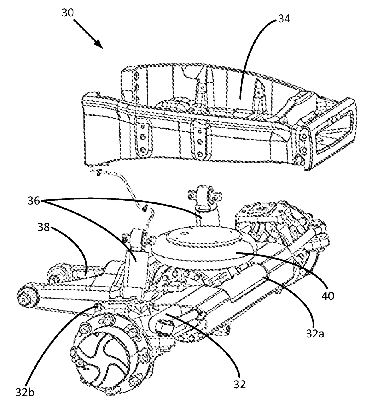
This patent describes a suspension system for a tractor that reduces the cost and weight of the system compared to previous designs. The system uses an air bellows located between the front axle and the front frame portion, which eliminates the need for additional subframes to support the bellows. This reduces the components and makes the front axle easier to service. The system also includes first and second shock absorbers to provide proper damping. By directly connecting the air bellows to the axle and frame, the need for additional components is eliminated, resulting in a less expensive and lighter system. The front frame portion also includes a hinge stop to prevent excessive hinging of the swing frame and the front axle. The system can also adjust operation based on changes in the ground profile in front of the suspension system, providing predictive control of the suspension system.

Problems solved by technology

While the Aires system provides for improved ride smoothness for operators, the system is not without drawbacks.
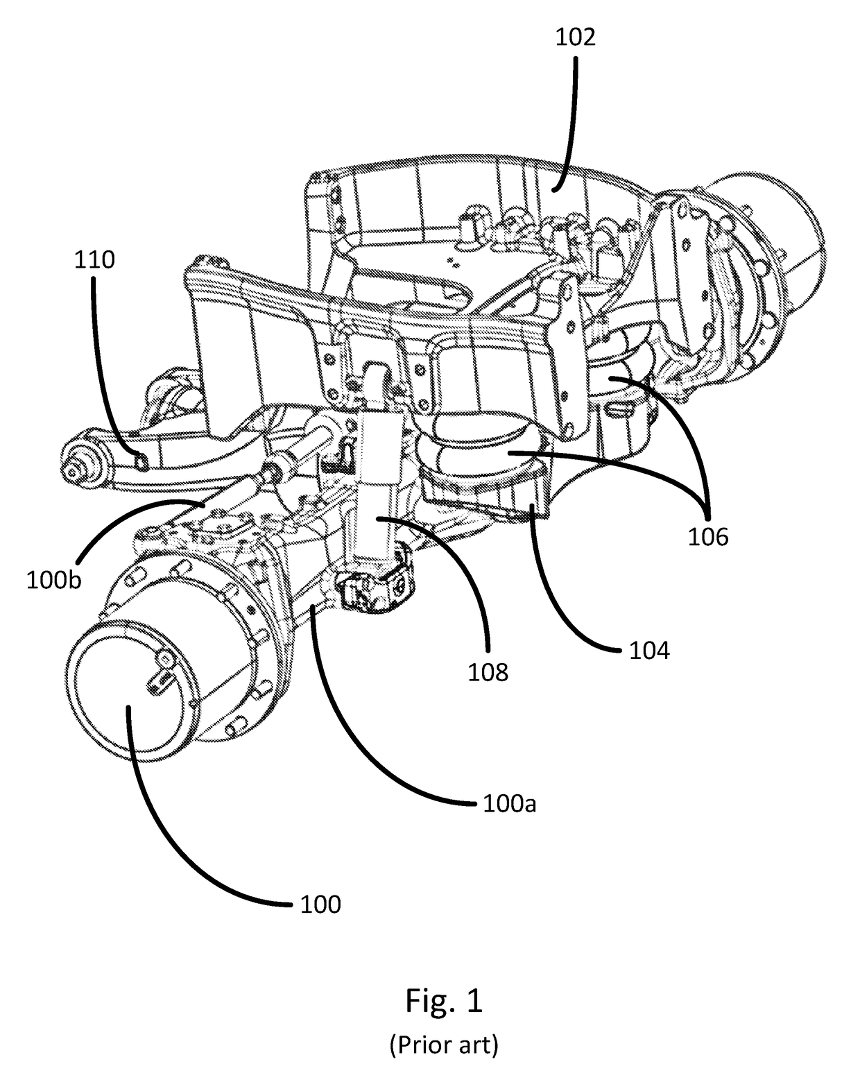
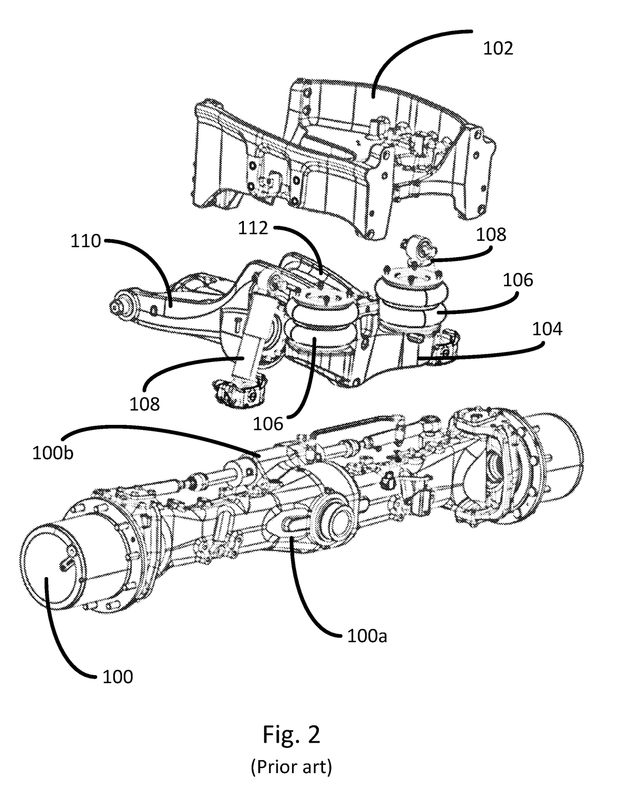
Firstly, the use of additional subframes to support the air bellows introduces additional cost and weight into the overall tractor designs.
Also, as the subframes require attachments to the front axle, this results in additional complication during servicing or repair of the front axle of the tractor.
Such a construction requires that each axle is tailor-made for the vehicle and application in question, which increases component cost and design complexity.
In addition, any servicing of the suspension system itself requires disassembly of the entire front axle.

Method used


Image

  • Axle suspension system for a tractor
  • Axle suspension system for a tractor
  • Axle suspension system for a tractor

Examples


Embodiment Construction

[0042]In FIG. 3, a vehicle in the form of an agricultural tractor is indicated at 10. The tractor 10 comprises front wheels 12, rear wheels 14, an engine section 16 and a cab section 18. The tractor 10 is provided with a structural frame 20, which extends between the front and rear wheels 12,14, providing structural support for the tractor body as it travels on the ground 22.

[0043]The tractor 10 further comprises at least one Electronic Control Unit (ECU) 24, which is arranged to control operation of various tractor systems. The cab section 18 is provided with operator controls 26 for control of the different components of the tractor 10. The operator controls 26 may comprise mechanical levers and / or electronic control systems incorporating configurable switches, touchscreen displays, etc. It will be understood that the ECU 24 is provided in communication with the operator controls 26. The tractor 10 further comprises at least one air compressor 28 controlled by the ECU 24, the air ...


PUM


Abstract

An axle suspension system for a front axle of a tractor using shock absorbers and an air bellows between the front axle and a front frame portion of the tractor to control the height of the front frame portion relative to the front axle. The position of the front frame portion may be maintained at a substantially constant vertical position, providing for improved driver comfort. The air bellows are positioned between the front axle and the front frame portion, thereby eliminating the need for additional mounting subframes in the suspension system.

Description

BACKGROUND[0001]Field of the Invention[0002]The present invention relates to a suspension system for an axle of an agricultural vehicle, in particular for a front axle of an agricultural tractor.[0003]Description of Related Art[0004]In vehicles intended for off-road operation, such as agricultural tractors, ride suspension systems are used to provide for increased operator comfort.[0005]An example of a known suspension system is the Aires front axle air suspension system produced by Valtra Oy Ab of Finland for agricultural tractors. With reference to FIGS. 1 and 2, the Aires system comprises a front axle 100 positioned beneath a front portion 102 of the structural frame of the tractor. The system comprises a subframe portion 104 which is attached to the front axle 100, at a forward-facing side 100a of the front axle 100. A pair of air bellows 106 are mounted to the subframe 104 and used to support the front frame portion 102. Shock absorbers 108 are arranged to extend between the ax...

Claims


Application Information

Patent Timeline
IPC IPC(8): B60G11/28B60G17/016B60G17/015
CPCB60G11/28B60G17/016B60G17/0155B60G9/02B60G11/27B60G2200/30B60G2202/152B60G2300/082B60G17/00B60G2300/08
Inventor PUUSTINEN, SAMI
Owner AGCO INT GMBH
Learn More