Aircraft and associated method for providing electrical energy to an Anti-icing system

Active Publication Date: 2017-07-27
THE BOEING CO
View PDF6 Cites 21 Cited by
  • Summary
  • Abstract
  • Description
  • Claims
  • Application Information

AI Technical Summary

Benefits of technology

[0007]An aircraft, an aircraft engine and a method are provided in accordance with an example embodiment in order to provide anti-icing functionality without adversely impacting the size of the aircraft engines. In this regard, electrical current may be provided to resistors carried by, such as by being embedded within, the flaps or other control surfaces with the electrical current being drawn from the fan assembly, such as from rotation of the low pressure shaft of the fan assembly, of an air

Problems solved by technology

The accumulation of ice on the, wings, flaps, and other control surfaces of an aircraft may be detrimental to the performance of the aircraft.
However, the heated air may have a temperature that is so high that the ductwork required to route the heated air to the flaps or other control surfaces must be made of materials that are specifically adapted to withstand such elevated temperatures, thereby increasing the cost of the ductwork.
Although the pre-cooler is able to cool the bleed air extracted from the aircraft engine to a suitable temperature for anti-icing purposes, the elevated temperature of the bleed air may cause the size of the pre-cooler to be increased which, in turn, may cause the size of the ductwork in which the pre-cooler is disposed to correspondingly increase.
Since space onboard an aircraft is limited, any increase in the size of the ductwork may be disadvantageous.
Additionally, pneumatic anti-icing systems may sometimes weigh more and be more complex

Method used


Image

  • Aircraft and associated method for providing electrical energy to an Anti-icing system
  • Aircraft and associated method for providing electrical energy to an Anti-icing system
  • Aircraft and associated method for providing electrical energy to an Anti-icing system

Examples


Embodiment Construction

[0022]Embodiments of the present disclosure now will be described more fully hereinafter with reference to the accompanying drawings, in which some, but not all embodiments are shown. Indeed, these embodiments may be embodied in many different forms and should not be construed as limited to the embodiments set forth herein; rather, these embodiments are provided so that this disclosure will satisfy applicable legal requirements. Like numbers refer to like elements throughout.

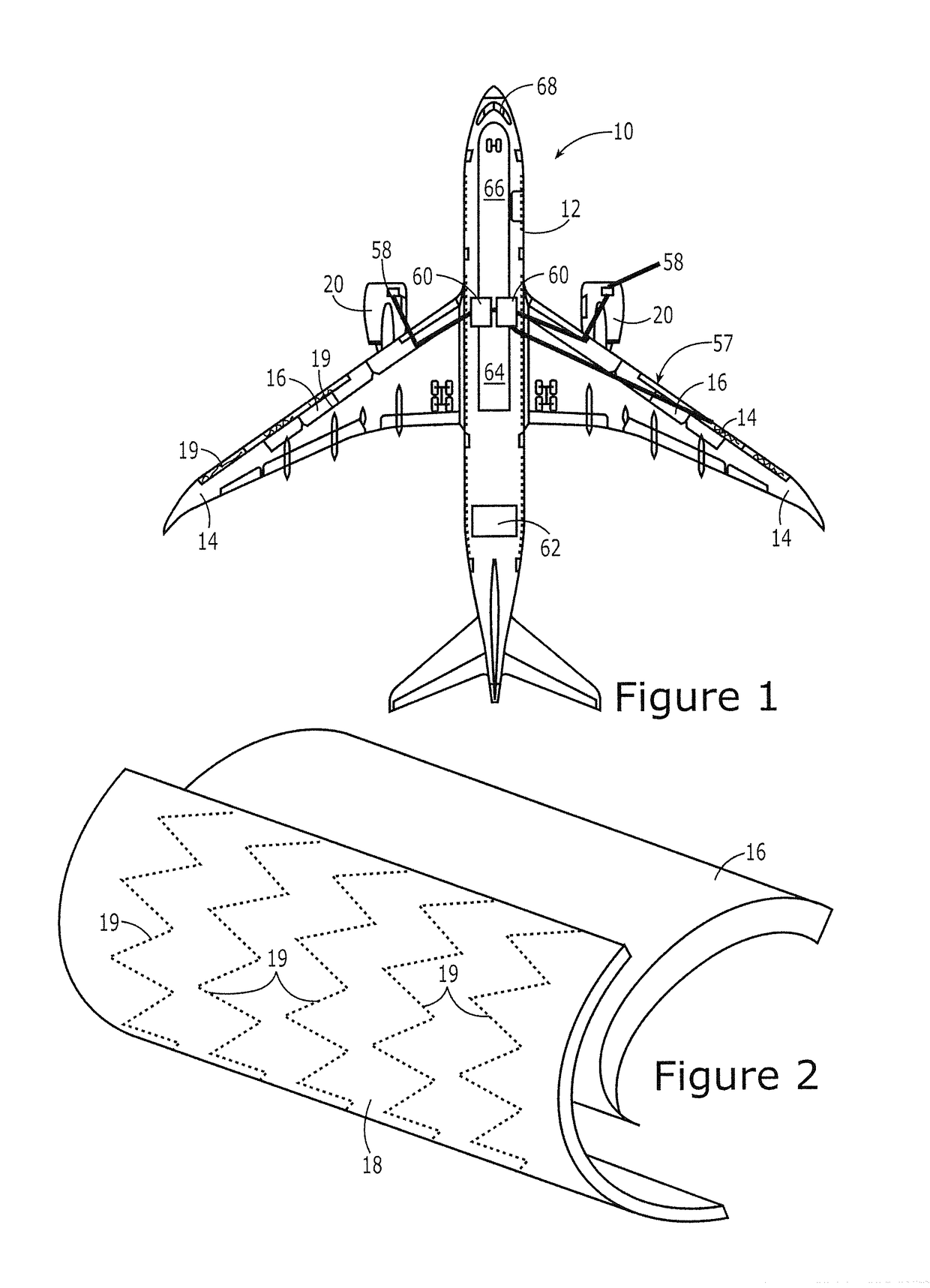
[0023]As shown in FIG. 1, an aircraft 10 generally includes an aircraft body 12 having two or more wings 14 extending laterally outward therefrom. The aircraft 10 may include flaps 16 and other control surfaces for facilitating the controlled flight of the aircraft. At least some of the flaps 16 are disposed along the leading edge of the wings 14. In the example embodiment depicted in FIG. 1, the wings 14 may include a plurality of flaps 16 along their leading edges with each flap configured to be controllably d...


PUM


Abstract

An aircraft, an aircraft engine and a corresponding method provide for anti-icing based upon energy provided by a fan assembly of the aircraft engine, such as by rotation of a low pressure shaft of the fan assembly. The aircraft includes an aircraft body having wings and an aircraft engine carried by the aircraft body. The aircraft engine includes a core gas turbine engine and a fan assembly coupled to the core gas turbine engine. The fan assembly may include a fan, a low pressure turbine and a low pressure shaft connecting the fan and the low pressure turbine. The aircraft engine also includes an electric anti-icing system that has a variable frequency generator driven by the fan assembly, and one or more resistive heaters carried by the wings. The variable frequency generator is configured to provide electrical energy to the one or more resistive heaters.

Description

TECHNOLOGICAL FIELD[0001]An example embodiment relates generally to a technique for controllably anti-icing an aircraft and, more particularly, to providing electrical energy to an anti-icing system from a variable frequency generator driven by a low pressure shaft of an aircraft engine.BACKGROUND[0002]The accumulation of ice on the, wings, flaps, and other control surfaces of an aircraft may be detrimental to the performance of the aircraft. As such, many aircraft include anti-icing systems for preventing or reducing the accumulation of ice during flight. For example, aircraft can include a pneumatic anti-icing system that directs heated air to the flaps and other control surfaces in order to prevent or reduce icing of those surfaces. Alternatively, aircraft may include an electrical anti-icing system that relies upon resistors embedded in the surface of the aircraft to heat the respective surfaces as current flows therethrough.[0003]With respect to a pneumatic anti-icing system, h...

Claims


Application Information

Patent Timeline
IPC IPC(8): B64D15/12B64D27/10B64D33/00
CPCB64D15/12B64D2221/00B64D27/10B64D33/00F01D15/10F02C6/00F05D2220/76Y02T50/60
Inventor MACKIN, STEVE G.
Owner THE BOEING CO
Why Eureka
Try Eureka