Spacecraft propulsion system and method

a propulsion system and spacecraft technology, applied in the field of electric thrusters, can solve problems such as the complexity of the system

Inactive Publication Date: 2017-07-27
SN DETUDE & DE CONSTR DE MOTEURS DAVIATION S N E C M A
View PDF9 Cites 12 Cited by
  • Summary
  • Abstract
  • Description
  • Claims
  • Application Information

AI Technical Summary

Benefits of technology

[0006]The present invention seeks to remedy those drawbacks. In particular, this disclosure seeks to propose a space propulsion system that makes it possible to offer at least a first propulsion mode with high specific impulse and low thrust, and a second propulsion mode with higher thrust but lower specific impulse than the first propulsion mode, but with specific impulse that is nevertheless greater than that which can be supplied by cold gas thrusters, and to do so with an electrical power supply circuit that is relatively simple.

Problems solved by technology

Nevertheless, since the specific impulse of cold gas thrusters is very limited, they consume a large amount of propellant fluid for high-thrust maneuvers, and in addition, in that system, there is little sharing of resources between the various types of thruster, resulting in the system being rather complex.

Method used


Image

  • Spacecraft propulsion system and method
  • Spacecraft propulsion system and method
  • Spacecraft propulsion system and method

Examples


first embodiment

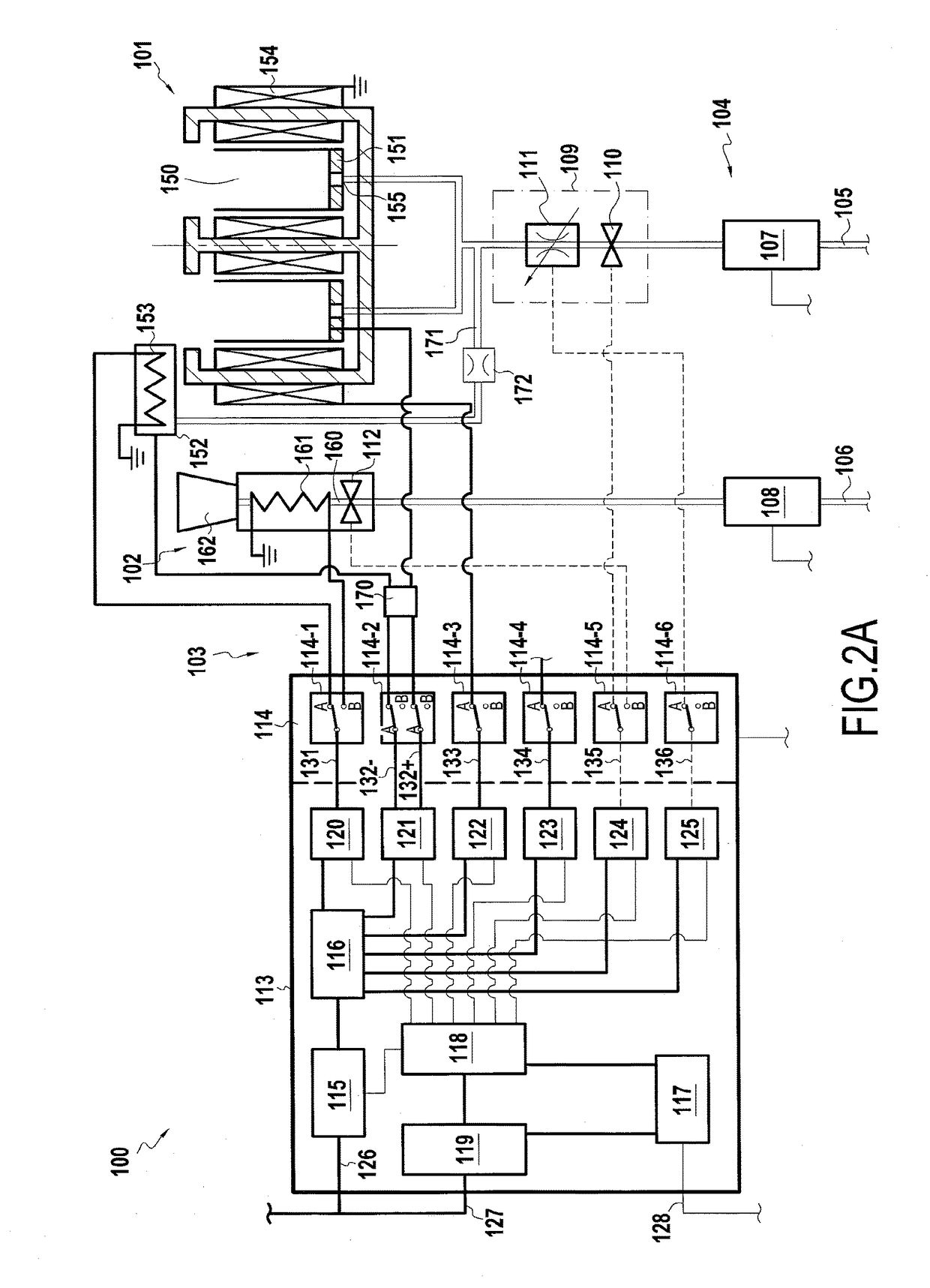
[0025]FIGS. 2A and 2B show a space propulsion system 100 in a The space propulsion system 100 comprises an electrostatic thruster 101 and a resistojet 102. In addition, it also has an electrical power supply circuit 103 and a propellant fluid feed circuit 104, both connected to both thrusters in order to supply them respectively with electricity and propellant fluid. The electrical power supply circuit 103 is connected to the electrical power supply 13 of the spacecraft 10 via the bus 14. The propellant fluid feed circuit 104 is connected to the tank 15.

[0026]The electrostatic thruster 101, which is more specifically a Hall effect thruster, comprises a channel 150 of annular section that is closed at its upstream end and open at its downstream end, an anode 151 situated at the upstream end of the channel 150, an emitter cathode 152 situated downstream from the downstream end of the channel 150 and fitted with at least one heater element 153, electromagnets 154 situated radially ins...

fourth embodiment

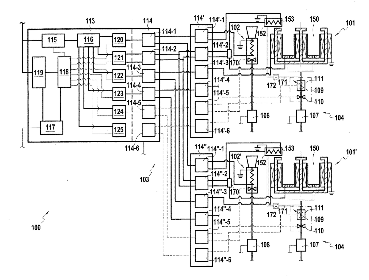
[0046]Although the space propulsion system in the three above-described embodiments has only one electrostatic thruster and only one resistojet, the same principles are equally applicable to systems having a plurality of electrostatic thrusters and of resistojets. Thus, in a fourth embodiment shown in FIG. 5, the space propulsion system 100 has two electrostatic thrusters 101 and two resistojets 102, e.g. arranged as thruster pairs, each pair being formed by one electrostatic thruster 101 and one resistojet 102, the thrusters in one of the pairs pointing in the opposite direction to the thrusters in the other pair. The two electrostatic thrusters 101 are connected to a single regulator 107 for regulating the pressure at which propellant gas is fed to the electrostatic thrusters 101 by corresponding propellant fluid feed lines 105, while the two resistojets 102 are likewise connected to a single regulator 108 for regulating the pressure at which propellant gas is fed to the resistoje...


PUM


Abstract

A space propulsion system includes an electrostatic thruster with a first electrical load; a resistojet; a propellant fluid feed circuit; and an electrical power supply circuit including a first power supply line and a first switch for selecting between connecting the first power supply line to the resistojet and connecting the first power supply line to the first electrical load of the electrostatic thruster. The propulsion system thus enables a space propulsion method to be applied that includes a switching step for selecting a first propulsion mode in which the resistojet is activated, or a second propulsion mode in which the electrostatic thruster is activated.

Description

BACKGROUND OF THE INVENTION[0001]The present invention relates to the field of space propulsion.[0002]In this field, electric thrusters are becoming more and more frequent, in particular for controlling the attitude and the orbit of spacecraft. Specifically, the various types of electric thruster available provide specific impulse that is generally greater than that of conventional chemical or cold gas thrusters, thus making it possible to reduce the consumption of propellant fluid for the same maneuvers, thereby increasing the lifetime and / or the payload of spacecraft.[0003]Among the various types of electric thruster, two categories are known in particular: so-called thermoelectric thrusters in which the propellant fluid is heated electrically prior to expanding in a thrust nozzle, and so-called electrostatic thrusters in which the propellant fluid is ionized and accelerated directly by an electric field. Among thermoelectric thrusters, there are in particular those known as “resi...

Claims


Application Information

Patent Timeline
Patent Type & Authority Applications(United States)
IPC IPC(8): B64G1/40B64G1/26F03H1/00B64G1/44
CPCB64G1/406B64G1/443B64G1/26F03H1/0018F03H1/0075F03H1/0012B64G1/405B64G1/428B64G1/402B64G1/415B64G1/42F03H1/00
Inventor MARCHANDISE, FREDERIC
Owner SN DETUDE & DE CONSTR DE MOTEURS DAVIATION S N E C M A
Why Eureka
Try Eureka