
Shelving Apparatus

Inactive Publication Date: 2017-07-27
TSAI FRANK
View PDF0 Cites 9 Cited by
  • Summary
  • Abstract
  • Description
  • Claims
  • Application Information

AI Technical Summary

Benefits of technology

The invention is a shelving apparatus that allows for easy assembly and disassembly of post members. The post members can be detachably coupled end-to-end, allowing for adjustable height and different supporting orientations. The post locker prevents twisting movement and provides a rigid structure to connect post members. The shelving apparatus can be expanded longitudinally by coupling two shelf supporting beam configurations to a single post. The foldable post is pivotally coupled end-to-end for better assembly and disassembly.

Problems solved by technology

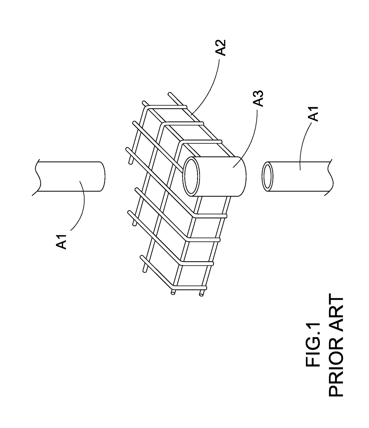
However, after the objects are loaded and supported by the shelving unit, the overall weight of the objects will exerted to the vertical posts via the supporting panel.
In addition, when one of the tubular connectors A3 is broken or damaged, the supporting panels cannot be securely coupled to the vertical posts any more.
Therefore, the material cost of the shelving unit will be substantially high and the size of the shelving unit will be enlarged.
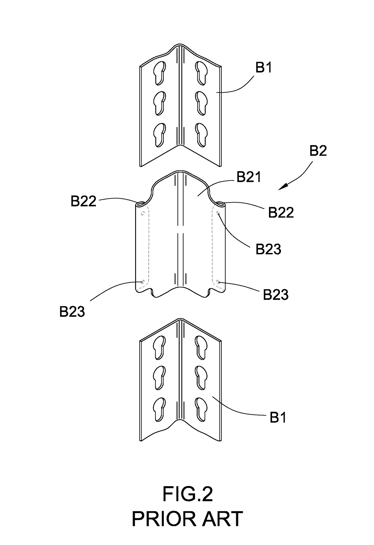
However, due to the frictional engagement between the end portion of the post member B1 and the coupler B2, the user may not able to correctly insert the end portion of the post member B1 into the gap of the coupler B2.
It is unstable for the shelf structure when the end portion of the post member B1 cannot be fully inserted into the gap of the coupler B2.
The excessive inserting force of the end portion of the post member B1 will damage the structure of the coupler B2 and will enlarge the size of the gap thereof.
Furthermore, such shaped detachable connecting structure cannot solve the same problem of how to easily disassemble the shelving unit.
The overall structure of the shelving unit become wobble and unstable.
In addition, when one of the couplers B2 is lost or damaged, the post members B1 cannot be coupled end-to-end any more.

Method used


Image

  • Shelving Apparatus
  • Shelving Apparatus
  • Shelving Apparatus

Examples


second embodiment

[0158]The supporting frame 10E has the same structure of the above second embodiment, wherein the supporting frame 10E is detachably coupling with the posts 20E to form the shelving apparatus, wherein the supporting frame 10E comprises one or more shelf supporting beam configurations.

[0159]Each of the shelf supporting beam configurations comprises a shelf platform 11E, a plurality of shelf retaining members 12E and a shelf supporting arrangement 13E, wherein the shelf retaining members 12E are each detachably coupled with two of the posts 20E to form a boundary frame to support the shelf platform 11E therewithin.

[0160]Each of the shelf retaining members 12E has two coupling ends 120E arranged detachably coupling with two of the posts 20E in the unfolded condition, and first and second longitudinal edges 121E, 122E extended between the two coupling ends 120E, wherein the shelf supporting arrangement 13E is integrally extended from each of the shelf retaining members 12E between the f...

first embodiment

[0162]It is worth mentioning that the shelf retaining member 12E can be configured to have the same structural configuration of the It is worth mentioning that the head 1231E of the fastener 123E is inserted through the upper hole portion 231E of the keyhole 23E, the keyhole guider 233E will guide the head 1231E of the fastener 123E to prevent the head 1231E of the fastener 123E not to over insert into post cavity 210E, so as to ensure the head 1231E of the fastener 123E to slide into the lower hole portion 232E of the corresponding keyhole 23E from the upper hole portion 231E.

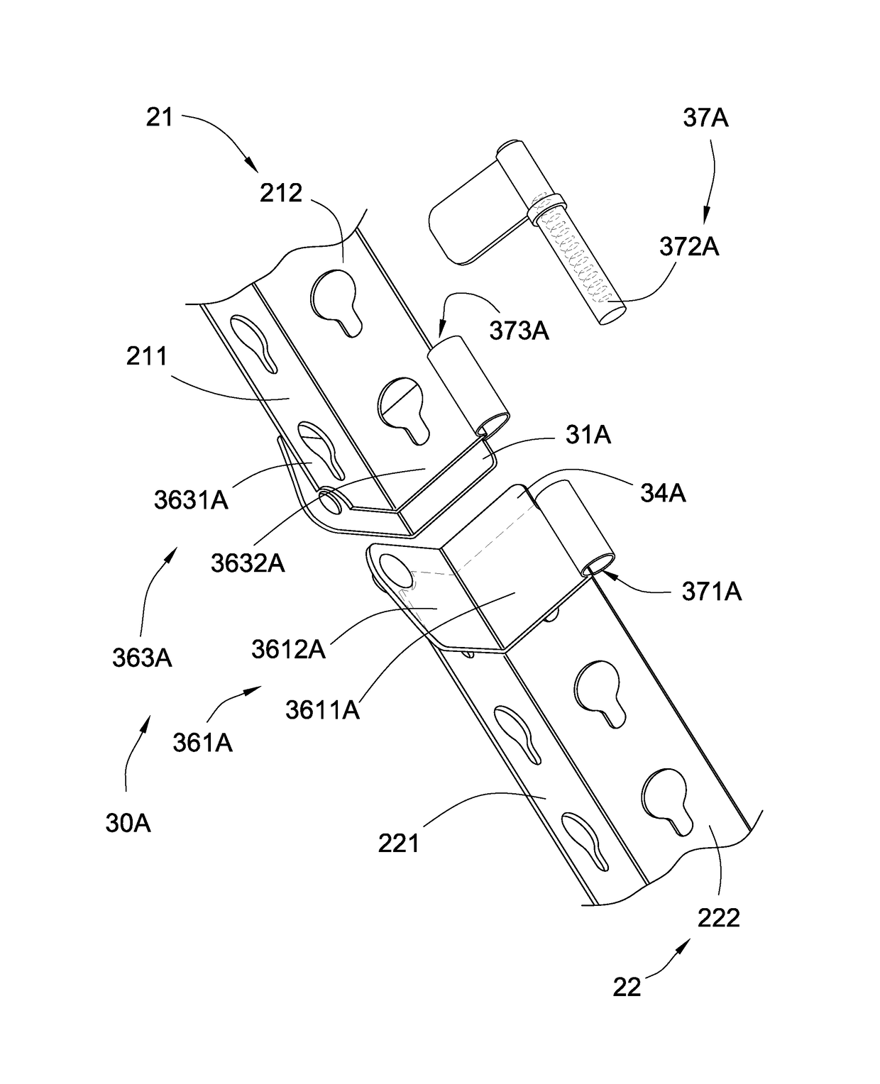
[0163]It is worth mentioning that when the engaging tongue 31E is inserted into the upper and lower post members 21E, 22E to couple the upper and lower post members 21E, 22E end-to-end, the fastener 123E is inserted into the post cavity 210E through the keyhole 23E and is also inserted through the guiding slot 32E of the post joint 30E.

[0164]The shelf platform 11E also has the similar structural configuration...

third embodiment

[0201]According to the preferred, the shelving apparatus is constructed to include both the post 20E and the post 20F of the third embodiment and its alternative to selectively expand the longitudinal size of the shelving apparatus. Accordingly, two shelf retaining members 12E can be detachably coupled at the upper or lower post member 21F, 22F side-by-side to selectively expand the longitudinal size of the shelving structure by coupling two shelf retaining members 12E to two sides of one single post 20F respectively. In other words, the T-shaped post 20F allows two shelf retaining members 12E to couple at two sides thereof at opposite directions.

[0202]As shown in FIG. 28, a shelving apparatus according to a fifth embodiment illustrates a modification of the fourth embodiment, wherein the post 20G of the fifth embodiment is an alternative mode of the fourth embodiment. As shown in FIGS. 28 and 29, each of the posts 20G, which generally has a T-shaped configuration, comprises at leas...


PUM

PropertyMeasurementUnit
Angleaaaaaaaaaa
Distanceaaaaaaaaaa

Abstract

A shelving apparatus includes a supporting frame and a plurality of posts for coupling with the supporting frame. Each post includes an upper post member, a lower post member and a post joint, wherein each of the upper and lower post members has a first post wall and a second post wall extended from the first wall at an angle. The post joint includes an engaging tongue extended into interiors of an end portion of the upper post member and an end portion of the lower post member, such that the upper and lower post members are interlocked and coupled with each other end-to-end.

Description

CROSS REFERENCE OF RELATED APPLICATION[0001]This is a Continuation-In-Part application that claims the benefit of priority under 35 U.S.C.§119 to a first non-provisional application, application Ser. No. 15 / 004,986, filed Jan. 24, 2016, a second non-provisional application, application Ser. No. 15 / 004,987, filed Jan. 24, 2016, a third non-provisional application, application Ser. No. 15 / 004,989, filed Jan. 24, 2016, and a fourth non-provisional application, application Ser. No. 15 / 047,648, filed Feb. 19, 2016.NOTICE OF COPYRIGHT[0002]A portion of the disclosure of this patent document contains material which is subject to copyright protection. The copyright owner has no objection to any reproduction by anyone of the patent disclosure, as it appears in the United States Patent and Trademark Office patent files or records, but otherwise reserves all copyright rights whatsoever.BACKGROUND OF THE PRESENT INVENTION[0003]Field of Invention[0004]The present invention relates to a shelf str...

Claims


Application Information

Patent Timeline
IPC IPC(8): F16B12/34A47B47/02A47B47/00A47B96/14A47B57/34A47B96/02
CPCF16B12/34A47B57/34A47B96/021A47B47/021A47B96/145A47B96/1441A47B47/0083A47B96/061
Inventor TSAI, FRANK
Owner TSAI FRANK
Learn More